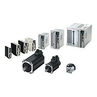
近年,業界以歐洲市場為主體,對於以國際規範IEC 61800-5-2 (EN61800-5-2)為依循的安全停止機能、安全監控功能等之要求一年比一年來得更嚴格。
本公司備有AC伺服系統1S系列SS1/SLS搭載型,能滿足前述需求。

![R88D-1SN[]-ECT-51](/upload/product/omron/bot/omron_3923/picture.jpg)
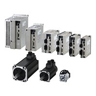
近年,業界以歐洲市場為主體,對於以國際規範IEC 61800-5-2 (EN61800-5-2)為依循的安全停止機能、安全監控功能等之要求一年比一年來得更嚴格。
本公司備有AC伺服系統1S系列SS1/SLS搭載型,能滿足前述需求。
![R88D-1SN[]-ECT-51 特長 1](/upload/product/omron/bot/omron_3923/e420707c6503af8ad2707736b6741004.jpg)
![R88D-1SN[]-ECT-51 特長 2](/upload/product/omron/bot/omron_3923/f8ac0f829eb48a4a066bc521ae4ca387.jpg)
![R88D-1SN[]-ECT-51 特長 3](/upload/product/omron/bot/omron_3923/c9e1e88145c8b0bb2e01470454b4a9e3.jpg)
此功能可中斷馬達電力供應,並停止馬達動作。
![R88D-1SN[]-ECT-51 特長 4](/upload/product/omron/bot/omron_3923/973ec7eace5519a6b1bfe3ea5fb07461.jpg)
此功能可在SS1啟動並經過指定時間後,利用STO讓馬達安全停機。此功能屬於停止類別1,因此可作為ISO13840所定義的緊急停機功能使用。
![R88D-1SN[]-ECT-51 特長 5](/upload/product/omron/bot/omron_3923/2c719bc465e250e6dab98f4d0b1ddcf9.jpg)
此功能可讓馬達保持所指定的速度。
![R88D-1SN[]-ECT-51 特長 6](/upload/product/omron/bot/omron_3923/00ca3fab3257c3b6d11255822a708592.jpg)
1S系列伺服系統的設計理念,在於提升裝置從設計、啟動至維修等各作業的效率,以滿足客戶多元的需求。 此外,採用無電池ABS編碼器,並具備相同網路架構下的安全性和高速高精密度控制,可提升裝置生產效率。
![R88D-1SN[]-ECT-51 特長 8](/upload/product/omron/bot/omron_3923/425eb2bd6b07694a37242cdeacefe7b6.jpg)
*1. 15kW (200V)除外
使用多軸簡易調整功能,即可在同時運轉的狀態下預估負載慣性慣量,藉由簡易的操作動作就能完成調整作業。
![R88D-1SN[]-ECT-51 特長 9](/upload/product/omron/bot/omron_3923/97deac6dd141d7c66aea706b740ec65f.jpg)
符合FSoE規範,透過EtherCAT纜線,即可建構安全系統,而且不需要增加配線。如此,當製作好的裝置加以拆解,並運送到國外時, 由於符合FSoE規範,即可精簡配線,並且減少重新配線所需的工時。 除了NJ/NX機械自動化控制器系列,亦適用於OMRON商品PMAC多軸動作控制器系列*2。
![R88D-1SN[]-ECT-51 特長 11](/upload/product/omron/bot/omron_3923/1579ee336a8e1fa03084c183e95ccc84.jpg)
控制器和伺服裝置僅需要使用單一軟體即可完成設定。所有的伺服裝置皆可利用EtherCAT進行設定, 無需插拔纜線,因此能減少設定所需工時。
![R88D-1SN[]-ECT-51 特長 12](/upload/product/omron/bot/omron_3923/466c165b9dacd65782beac034a9a6421.jpg)
● 利用安全程式模擬功能,即可縮短除錯所需的時間
● 安全程式自動產生功能
● 安全參數全部備份功能
● 安全參數可依裝置的單位別顯示,更能一目瞭然
● 自動計算安全任務的週期
![R88D-1SN[]-ECT-51 特長 13](/upload/product/omron/bot/omron_3923/6bd3e7fc44f51069ed0f83b8152b92a1.jpg)
![R88D-1SN[]-ECT-51 特長 15](/upload/product/omron/bot/omron_3923/a0e401024d3216e6043c46bbc4507009.jpg)
![R88D-1SN[]-ECT-51 特長 16](/upload/product/omron/bot/omron_3923/af6c501f0d0f7e5fedbc9a41ba179c0d.jpg)
● 將運動控制、邏輯、安全、驅動器、影像感測器和HMI的支援功能整合至一套軟體內
● 符合開放式程式國際標準IEC 61131-3 (及JIS B 3503)
● 符合PLCopen的運動控制、安全功能區塊
● 支援對應變數的指令語言,如階梯圖語言、ST語言及功能區塊程式設計
● 配備CAM編輯器,可輕鬆設定複雜的運動控制
● 連接資料庫的功能區塊
● 可用於機械自動化控制器NJ/NX系列程式的軟體功能元件庫。也備有樣品程式與HMI畫面樣品
Sysmac為OMRON Corporation製造之FA機器產品於日本及其他國家之商標或註冊商標。Windows、SQL Server為美國Microsoft Corporation於美國、日本及其他國家之註 冊商標或商標。EtherCAT®及Safety over EtherCAT®為註冊商標及已經取得專利的技術,已獲得Beckhoff Automation GmbH (德國)的授權。EtherNet/IP™、CIP Safety™ 為ODVA之商標。本型錄所刊載之其他公司名稱及產品名稱等,為各公司之註冊商標或商標。本型錄所使用的產品照片或圖片中包含示意圖,可能和實物不同。所使用之畫 面擷圖,均已取得微軟公司授權許可。包含Shutterstock.com已授權使用之圖片。
![R88D-1SN[]-ECT-51 種類 1](/upload/product/omron/bot/omron_3923/2349d3230fda3b62adc528f649cd39b4.gif)
![R88D-1SN[]-ECT-51 種類 2](/upload/product/omron/bot/omron_3923/67dee012d0637591f81ae930c40358f7.gif)
![R88D-1SN[]-ECT-51 種類 3](/upload/product/omron/bot/omron_3923/d42bbb5a63913ac9d2f66f07d1338f8b.gif)
| Power supply voltage | Rated output | Model |
|---|---|---|
| Single-phase 100 VAC | 100 W | R88D-1SN01L-ECT-51 |
| 200 W | R88D-1SN02L-ECT-51 | |
| 400 W | R88D-1SN04L-ECT-51 | |
| Single-phase/3-phase 200 VAC | 100 W | R88D-1SN01H-ECT-51 |
| 200 W | R88D-1SN02H-ECT-51 | |
| 400 W | R88D-1SN04H-ECT-51 | |
| 750 W | R88D-1SN08H-ECT-51 | |
| 1.5 kW | R88D-1SN15H-ECT-51 | |
| 3-phase 200 VAC | 1 kW | R88D-1SN10H-ECT-51 |
| 2 kW | R88D-1SN20H-ECT-51 | |
| 3 kW | R88D-1SN30H-ECT-51 | |
| 5.5 kW | R88D-1SN55H-ECT-51 | |
| 7.5 kW | R88D-1SN75H-ECT-51 | |
| 15 kW | R88D-1SN150H-ECT-51 | |
| 3-phase 400 VAC | 600 W | R88D-1SN06F-ECT-51 |
| 1 kW | R88D-1SN10F-ECT-51 | |
| 1.5 kW | R88D-1SN15F-ECT-51 | |
| 2 kW | R88D-1SN20F-ECT-51 | |
| 3 kW | R88D-1SN30F-ECT-51 | |
| 5.5 kW | R88D-1SN55F-ECT-51 | |
| 7.5 kW | R88D-1SN75F-ECT-51 | |
| 15 kW | R88D-1SN150F-ECT-51 |
| Specifications | Model | |||
|---|---|---|---|---|
| Without oil seal | ||||
| Straight shaft | With key and tap | |||
| Without brake | 100 VAC | 50 W | R88M-1M05030S | R88M-1M05030S-S2 |
| 100 W | R88M-1M10030S | R88M-1M10030S-S2 | ||
| 200 W | R88M-1M20030S | R88M-1M20030S-S2 | ||
| 400 W | R88M-1M40030S | R88M-1M40030S-S2 | ||
| 200 VAC | 50 W | R88M-1M05030T | R88M-1M05030T-S2 | |
| 100 W | R88M-1M10030T | R88M-1M10030T-S2 | ||
| 200 W | R88M-1M20030T | R88M-1M20030T-S2 | ||
| 400 W | R88M-1M40030T | R88M-1M40030T-S2 | ||
| 750 W | R88M-1M75030T | R88M-1M75030T-S2 | ||
| 1 kW | R88M-1L1K030T | R88M-1L1K030T-S2 | ||
| 1.5 kW | R88M-1L1K530T | R88M-1L1K530T-S2 | ||
| 2 kW | R88M-1L2K030T | R88M-1L2K030T-S2 | ||
| 3 kW | R88M-1L3K030T | R88M-1L3K030T-S2 | ||
| 4 kW | R88M-1L4K030T | R88M-1L4K030T-S2 | ||
| 4.7 kW | R88M-1L4K730T | R88M-1L4K730T-S2 | ||
| 400 VAC | 750 W | R88M-1L75030C | R88M-1L75030C-S2 | |
| 1 kW | R88M-1L1K030C | R88M-1L1K030C-S2 | ||
| 1.5 kW | R88M-1L1K530C | R88M-1L1K530C-S2 | ||
| 2 kW | R88M-1L2K030C | R88M-1L2K030C-S2 | ||
| 3 kW | R88M-1L3K030C | R88M-1L3K030C-S2 | ||
| 4 kW | R88M-1L4K030C | R88M-1L4K030C-S2 | ||
| 5 kW | R88M-1L5K030C | R88M-1L5K030C-S2 | ||
| With brake | 100 VAC | 50 W | R88M-1M05030S-B | R88M-1M05030S-BS2 |
| 100 W | R88M-1M10030S-B | R88M-1M10030S-BS2 | ||
| 200 W | R88M-1M20030S-B | R88M-1M20030S-BS2 | ||
| 400 W | R88M-1M40030S-B | R88M-1M40030S-BS2 | ||
| 200 VAC | 50 W | R88M-1M05030T-B | R88M-1M05030T-BS2 | |
| 100 W | R88M-1M10030T-B | R88M-1M10030T-BS2 | ||
| 200 W | R88M-1M20030T-B | R88M-1M20030T-BS2 | ||
| 400 W | R88M-1M40030T-B | R88M-1M40030T-BS2 | ||
| 750 W | R88M-1M75030T-B | R88M-1M75030T-BS2 | ||
| 1 kW | R88M-1L1K030T-B | R88M-1L1K030T-BS2 | ||
| 1.5 kW | R88M-1L1K530T-B | R88M-1L1K530T-BS2 | ||
| 2 kW | R88M-1L2K030T-B | R88M-1L2K030T-BS2 | ||
| 3 kW | R88M-1L3K030T-B | R88M-1L3K030T-BS2 | ||
| 4 kW | R88M-1L4K030T-B | R88M-1L4K030T-BS2 | ||
| 4.7 kW | R88M-1L4K730T-B | R88M-1L4K730T-BS2 | ||
| 400 VAC | 750 W | R88M-1L75030C-B | R88M-1L75030C-BS2 | |
| 1 kW | R88M-1L1K030C-B | R88M-1L1K030C-BS2 | ||
| 1.5 kW | R88M-1L1K530C-B | R88M-1L1K530C-BS2 | ||
| 2 kW | R88M-1L2K030C-B | R88M-1L2K030C-BS2 | ||
| 3 kW | R88M-1L3K030C-B | R88M-1L3K030C-BS2 | ||
| 4 kW | R88M-1L4K030C-B | R88M-1L4K030C-BS2 | ||
| 5 kW | R88M-1L5K030C-B | R88M-1L5K030C-BS2 | ||
| Specifications | Model | |||
|---|---|---|---|---|
| With oil seal | ||||
| Straight shaft | With key and tap | |||
| Without brake | 100 VAC | 50 W | R88M-1M05030S-O | R88M-1M05030S-OS2 |
| 100 W | R88M-1M10030S-O | R88M-1M10030S-OS2 | ||
| 200 W | R88M-1M20030S-O | R88M-1M20030S-OS2 | ||
| 400 W | R88M-1M40030S-O | R88M-1M40030S-OS2 | ||
| 200 VAC | 50 W | R88M-1M05030T-O | R88M-1M05030T-OS2 | |
| 100 W | R88M-1M10030T-O | R88M-1M10030T-OS2 | ||
| 200 W | R88M-1M20030T-O | R88M-1M20030T-OS2 | ||
| 400 W | R88M-1M40030T-O | R88M-1M40030T-OS2 | ||
| 750 W | R88M-1M75030T-O | R88M-1M75030T-OS2 | ||
| 1 kW | R88M-1L1K030T-O | R88M-1L1K030T-OS2 | ||
| 1.5 kW | R88M-1L1K530T-O | R88M-1L1K530T-OS2 | ||
| 2 kW | R88M-1L2K030T-O | R88M-1L2K030T-OS2 | ||
| 3 kW | R88M-1L3K030T-O | R88M-1L3K030T-OS2 | ||
| 4 kW | R88M-1L4K030T-O | R88M-1L4K030T-OS2 | ||
| 4.7 kW | R88M-1L4K730T-O | R88M-1L4K730T-OS2 | ||
| 400 VAC | 750 W | R88M-1L75030C-O | R88M-1L75030C-OS2 | |
| 1 kW | R88M-1L1K030C-O | R88M-1L1K030C-OS2 | ||
| 1.5 kW | R88M-1L1K530C-O | R88M-1L1K530C-OS2 | ||
| 2 kW | R88M-1L2K030C-O | R88M-1L2K030C-OS2 | ||
| 3 kW | R88M-1L3K030C-O | R88M-1L3K030C-OS2 | ||
| 4 kW | R88M-1L4K030C-O | R88M-1L4K030C-OS2 | ||
| 5 kW | R88M-1L5K030C-O | R88M-1L5K030C-OS2 | ||
| With brake | 100 VAC | 50 W | R88M-1M05030S-BO | R88M-1M05030S-BOS2 |
| 100 W | R88M-1M10030S-BO | R88M-1M10030S-BOS2 | ||
| 200 W | R88M-1M20030S-BO | R88M-1M20030S-BOS2 | ||
| 400 W | R88M-1M40030S-BO | R88M-1M40030S-BOS2 | ||
| 200 VAC | 50 W | R88M-1M05030T-BO | R88M-1M05030T-BOS2 | |
| 100 W | R88M-1M10030T-BO | R88M-1M10030T-BOS2 | ||
| 200W | R88M-1M20030T-BO | R88M-1M20030T-BOS2 | ||
| 400 W | R88M-1M40030T-BO | R88M-1M40030T-BOS2 | ||
| 750 W | R88M-1M75030T-BO | R88M-1M75030T-BOS2 | ||
| 1 kW | R88M-1L1K030T-BO | R88M-1L1K030T-BOS2 | ||
| 1.5 kW | R88M-1L1K530T-BO | R88M-1L1K530T-BOS2 | ||
| 2 kW | R88M-1L2K030T-BO | R88M-1L2K030T-BOS2 | ||
| 3 kW | R88M-1L3K030T-BO | R88M-1L3K030T-BOS2 | ||
| 4 kW | R88M-1L4K030T-BO | R88M-1L4K030T-BOS2 | ||
| 4.7 kW | R88M-1L4K730T-BO | R88M-1L4K730T-BOS2 | ||
| 400 VAC | 750 W | R88M-1L75030C-BO | R88M-1L75030C-BOS2 | |
| 1 kW | R88M-1L1K030C-BO | R88M-1L1K030C-BOS2 | ||
| 1.5 kW | R88M-1L1K530C-BO | R88M-1L1K530C-BOS2 | ||
| 2 kW | R88M-1L2K030C-BO | R88M-1L2K030C-BOS2 | ||
| 3 kW | R88M-1L3K030C-BO | R88M-1L3K030C-BOS2 | ||
| 4 kW | R88M-1L4K030C-BO | R88M-1L4K030C-BOS2 | ||
| 5 kW | R88M-1L5K030C-BO | R88M-1L5K030C-BOS2 | ||
| Specifications | Model | |||
|---|---|---|---|---|
| Without oil seal | ||||
| Straight shaft | With key and tap | |||
| Without brake | 200 VAC | 1 kW | R88M-1M1K020T | R88M-1M1K020T-S2 |
| 1.5 kW | R88M-1M1K520T | R88M-1M1K520T-S2 | ||
| 2 kW | R88M-1M2K020T | R88M-1M2K020T-S2 | ||
| 3 kW | R88M-1M3K020T | R88M-1M3K020T-S2 | ||
| 400 VAC | 400 W | R88M-1M40020C | R88M-1M40020C-S2 | |
| 600 W | R88M-1M60020C | R88M-1M60020C-S2 | ||
| 1 kW | R88M-1M1K020C | R88M-1M1K020C-S2 | ||
| 1.5 kW | R88M-1M1K520C | R88M-1M1K520C-S2 | ||
| 2 kW | R88M-1M2K020C | R88M-1M2K020C-S2 | ||
| 3 kW | R88M-1M3K020C | R88M-1M3K020C-S2 | ||
| With brake | 200 VAC | 1 kW | R88M-1M1K020T-B | R88M-1M1K020T-BS2 |
| 1.5 kW | R88M-1M1K520T-B | R88M-1M1K520T-BS2 | ||
| 2 kW | R88M-1M2K020T-B | R88M-1M2K020T-BS2 | ||
| 3 kW | R88M-1M3K020T-B | R88M-1M3K020T-BS2 | ||
| 400 VAC | 400 W | R88M-1M40020C-B | R88M-1M40020C-BS2 | |
| 600 W | R88M-1M60020C-B | R88M-1M60020C-BS2 | ||
| 1 kW | R88M-1M1K020C-B | R88M-1M1K020C-BS2 | ||
| 1.5 kW | R88M-1M1K520C-B | R88M-1M1K520C-BS2 | ||
| 2 kW | R88M-1M2K020C-B | R88M-1M2K020C-BS2 | ||
| 3 kW | R88M-1M3K020C-B | R88M-1M3K020C-BS2 | ||
| Specifications | Model | |||
|---|---|---|---|---|
| With oil seal | ||||
| Straight shaft | With key and tap | |||
| Without brake | 200 VAC | 1 kW | R88M-1M1K020T-O | R88M-1M1K020T-OS2 |
| 1.5 kW | R88M-1M1K520T-O | R88M-1M1K520T-OS2 | ||
| 2 kW | R88M-1M2K020T-O | R88M-1M2K020T-OS2 | ||
| 3 kW | R88M-1M3K020T-O | R88M-1M3K020T-OS2 | ||
| 400 VAC | 400 W | R88M-1M40020C-O | R88M-1M40020C-OS2 | |
| 600 W | R88M-1M60020C-O | R88M-1M60020C-OS2 | ||
| 1 kW | R88M-1M1K020C-O | R88M-1M1K020C-OS2 | ||
| 1.5 kW | R88M-1M1K520C-O | R88M-1M1K520C-OS2 | ||
| 2 kW | R88M-1M2K020C-O | R88M-1M2K020C-OS2 | ||
| 3 kW | R88M-1M3K020C-O | R88M-1M3K020C-OS2 | ||
| With brake | 200 VAC | 1 kW | R88M-1M1K020T-BO | R88M-1M1K020T-BOS2 |
| 1.5 kW | R88M-1M1K520T-BO | R88M-1M1K520T-BOS2 | ||
| 2 kW | R88M-1M2K020T-BO | R88M-1M2K020T-BOS2 | ||
| 3 kW | R88M-1M3K020T-BO | R88M-1M3K020T-BOS2 | ||
| 400 VAC | 400 W | R88M-1M40020C-BO | R88M-1M40020C-BOS2 | |
| 600 W | R88M-1M60020C-BO | R88M-1M60020C-BOS2 | ||
| 1 kW | R88M-1M1K020C-BO | R88M-1M1K020C-BOS2 | ||
| 1.5 kW | R88M-1M1K520C-BO | R88M-1M1K520C-BOS2 | ||
| 2 kW | R88M-1M2K020C-BO | R88M-1M2K020C-BOS2 | ||
| 3 kW | R88M-1M3K020C-BO | R88M-1M3K020C-BOS2 | ||
| Specifications | Model | |||
|---|---|---|---|---|
| Without oil seal | ||||
| Straight shaft | With key and tap | |||
| Without brake | 200 VAC | 4 kW | R88M-1M4K015T | R88M-1M4K015T-S2 |
| 5 kW | R88M-1M5K015T | R88M-1M5K015T-S2 | ||
| 7.5 kW | R88M-1M7K515T | R88M-1M7K515T-S2 | ||
| 11 kW | R88M-1M11K015T | R88M-1M11K015T-S2 | ||
| 15 kW | R88M-1M15K015T | R88M-1M15K015T-S2 | ||
| AC400V | 4 kW | R88M-1M4K015C | R88M-1M4K015C-S2 | |
| 5.5 kW | R88M-1M5K515C | R88M-1M5K515C-S2 | ||
| 7.5 kW | R88M-1M7K515C | R88M-1M7K515C-S2 | ||
| 11 kW | R88M-1M11K015C | R88M-1M11K015C-S2 | ||
| 15 kW | R88M-1M15K015C | R88M-1M15K015C-S2 | ||
| With brake | 200 VAC | 4 kW | R88M-1M4K015T-B | R88M-1M4K015T-BS2 |
| 5 kW | R88M-1M5K015T-B | R88M-1M5K015T-BS2 | ||
| 7.5 kW | R88M-1M7K515T-B | R88M-1M7K515T-BS2 | ||
| 11 kW | R88M-1M11K015T-B | R88M-1M11K015T-BS2 | ||
| 15 kW | R88M-1M15K015T-B | R88M-1M15K015T-BS2 | ||
| AC400V | 4 kW | R88M-1M4K015C-B | R88M-1M4K015C-BS2 | |
| 5.5 kW | R88M-1M5K515C-B | R88M-1M5K515C-BS2 | ||
| 7.5 kW | R88M-1M7K515C-B | R88M-1M7K515C-BS2 | ||
| 11 kW | R88M-1M11K015C-B | R88M-1M11K015C-BS2 | ||
| 15 kW | R88M-1M15K015C-B | R88M-1M15K015C-BS2 | ||
| Specifications | Model | |||
|---|---|---|---|---|
| With oil seal | ||||
| Straight shaft | With key and tap | |||
| Without brake | 200 VAC | 4 kW | R88M-1M4K015T-O | R88M-1M4K015T-OS2 |
| 5 kW | R88M-1M5K015T-O | R88M-1M5K015T-OS2 | ||
| 7.5 kW | R88M-1M7K515T-O | R88M-1M7K515T-OS2 | ||
| 11 kW | R88M-1M11K015T-O | R88M-1M11K015T-OS2 | ||
| 15 kW | R88M-1M15K015T-O | R88M-1M15K015T-OS2 | ||
| AC400V | 4 kW | R88M-1M4K015C-O | R88M-1M4K015C-OS2 | |
| 5.5 kW | R88M-1M5K515C-O | R88M-1M5K515C-OS2 | ||
| 7.5 kW | R88M-1M7K515C-O | R88M-1M7K515C-OS2 | ||
| 11 kW | R88M-1M11K015C-O | R88M-1M11K015C-OS2 | ||
| 15 kW | R88M-1M15K015C-O | R88M-1M15K015C-OS2 | ||
| With brake | 200 VAC | 4 kW | R88M-1M4K015T-BO | R88M-1M4K015T-BOS2 |
| 5 kW | R88M-1M5K015T-BO | R88M-1M5K015T-BOS2 | ||
| 7.5 kW | R88M-1M7K515T-BO | R88M-1M7K515T-BOS2 | ||
| 11 kW | R88M-1M11K015T-BO | R88M-1M11K015T-BOS2 | ||
| 15 kW | R88M-1M15K015T-BO | R88M-1M15K015T-BOS2 | ||
| AC400V | 4 kW | R88M-1M4K015C-BO | R88M-1M4K015C-BOS2 | |
| 5.5 kW | R88M-1M5K515C-BO | R88M-1M5K515C-BOS2 | ||
| 7.5 kW | R88M-1M7K515C-BO | R88M-1M7K515C-BOS2 | ||
| 11 kW | R88M-1M11K015C-BO | R88M-1M11K015C-BOS2 | ||
| 15 kW | R88M-1M15K015C-BO | R88M-1M15K015C-BOS2 | ||
| Specifications | Model | |||
|---|---|---|---|---|
| Without oil seal | ||||
| Straight shaft | With key and tap | |||
| Without brake | 200 VAC | 900 W | R88M-1M90010T | R88M-1M90010T-S2 |
| 2 kW | R88M-1M2K010T | R88M-1M2K010T-S2 | ||
| 3 kW | R88M-1M3K010T | R88M-1M3K010T-S2 | ||
| 400 VAC | 900 W | R88M-1M90010C | R88M-1M90010C-S2 | |
| 2 kW | R88M-1M2K010C | R88M-1M2K010C-S2 | ||
| 3 kW | R88M-1M3K010C | R88M-1M3K010C-S2 | ||
| With brake | 200 VAC | 900 W | R88M-1M90010T-B | R88M-1M90010T-BS2 |
| 2 kW | R88M-1M2K010T-B | R88M-1M2K010T-BS2 | ||
| 3 kW | R88M-1M3K010T-B | R88M-1M3K010T-BS2 | ||
| 400 VAC | 900 W | R88M-1M90010C-B | R88M-1M90010C-BS2 | |
| 2 kW | R88M-1M2K010C-B | R88M-1M2K010C-BS2 | ||
| 3 kW | R88M-1M3K010C-B | R88M-1M3K010C-BS2 | ||
| Specifications | Model | |||
|---|---|---|---|---|
| With oil seal | ||||
| Straight shaft | With key and tap | |||
| Without brake | 200 VAC | 900 W | R88M-1M90010T-O | R88M-1M90010T-OS2 |
| 2 kW | R88M-1M2K010T-O | R88M-1M2K010T-OS2 | ||
| 3 kW | R88M-1M3K010T-O | R88M-1M3K010T-OS2 | ||
| 400 VAC | 900 W | R88M-1M90010C-O | R88M-1M90010C-OS2 | |
| 2 kW | R88M-1M2K010C-O | R88M-1M2K010C-OS2 | ||
| 3 kW | R88M-1M3K010C-O | R88M-1M3K010C-OS2 | ||
| With brake | 200 VAC | 900 W | R88M-1M90010T-BO | R88M-1M90010T-BOS2 |
| 2 kW | R88M-1M2K010T-BO | R88M-1M2K010T-BOS2 | ||
| 3 kW | R88M-1M3K010T-BO | R88M-1M3K010T-BOS2 | ||
| 400 VAC | 900 W | R88M-1M90010C-BO | R88M-1M90010C-BOS2 | |
| 2 kW | R88M-1M2K010C-BO | R88M-1M2K010C-BOS2 | ||
| 3 kW | R88M-1M3K010C-BO | R88M-1M3K010C-BOS2 | ||
| Servomotor rated output | Reduction ratio | Model (Straight shaft) * |
|---|---|---|
| 50 W | 1/21 | R88G-HPG14A21100B[] |
| 1/33 | R88G-HPG14A33050B[] | |
| 1/45 | R88G-HPG14A45050B[] | |
| 100 W | 1/5 | R88G-HPG11B05100B[] |
| 1/11 | R88G-HPG14A11100B[] | |
| 1/21 | R88G-HPG14A21100B[] | |
| 1/33 | R88G-HPG20A33100B[] | |
| 1/45 | R88G-HPG20A45100B[] | |
| 200 W | 1/5 | R88G-HPG14A05200B[] |
| 1/11 | R88G-HPG14A11200B[] | |
| 1/21 | R88G-HPG20A21200B[] | |
| 1/33 | R88G-HPG20A33200B[] | |
| 1/45 | R88G-HPG20A45200B[] | |
| 400 W | 1/5 | R88G-HPG14A05400B[] |
| 1/11 | R88G-HPG20A11400B[] | |
| 1/21 | R88G-HPG20A21400B[] | |
| 1/33 | R88G-HPG32A33400B[] | |
| 1/45 | R88G-HPG32A45400B[] | |
| 750 W (200 V) |
1/5 | R88G-HPG20A05750B[] |
| 1/11 | R88G-HPG20A11750B[] | |
| 1/21 | R88G-HPG32A21750B[] | |
| 1/33 | R88G-HPG32A33750B[] | |
| 1/45 | R88G-HPG32A45750B[] | |
| 750 W (400 V) |
1/5 | R88G-HPG32A052K0B[] |
| 1/11 | R88G-HPG32A112K0B[] | |
| 1/21 | R88G-HPG32A211K5B[] | |
| 1/33 | R88G-HPG32A33600SB[] | |
| 1/45 | R88G-HPG50A451K5B[] | |
| 1 kW | 1/5 | R88G-HPG32A052K0B[] |
| 1/11 | R88G-HPG32A112K0B[] | |
| 1/21 | R88G-HPG32A211K5B[] | |
| 1/33 | R88G-HPG50A332K0B[] | |
| 1/45 | R88G-HPG50A451K5B[] | |
| 1.5 kW | 1/5 | R88G-HPG32A052K0B[] |
| 1/11 | R88G-HPG32A112K0B[] | |
| 1/21 | R88G-HPG32A211K5B[] | |
| 1/33 | R88G-HPG50A332K0B[] | |
| 1/45 | R88G-HPG50A451K5B[] | |
| 2 kW | 1/5 | R88G-HPG32A052K0B[] |
| 1/11 | R88G-HPG32A112K0B[] | |
| 1/21 | R88G-HPG50A212K0B[] | |
| 1/33 | R88G-HPG50A332K0B[] | |
| 3 kW | 1/5 | R88G-HPG32A053K0B[] |
| 1/11 | R88G-HPG50A113K0B[] | |
| 1/21 | R88G-HPG50A213K0B[] | |
| 4 kW | 1/5 | R88G-HPG32A054K0B[] |
| 1/11 | R88G-HPG50A115K0B[] | |
| 4.7 kW 5 kW |
1/5 | R88G-HPG50A055K0B[] |
| 1/11 | R88G-HPG50A115K0B[] |
* The standard shaft type is a straight shaft. A model with a key and tap is indicated with “J” at [] of the Decelerator model number.
e.g. R88G-HPG11B05100BJ
| Servomotor rated output | Reduction ratio | Model (Straight shaft) * |
|---|---|---|
| 400 W | 1/5 | R88G-HPG32A052K0B[] |
| 1/11 | R88G-HPG32A112K0B[] | |
| 1/21 | R88G-HPG32A211K5B[] | |
| 1/33 | R88G-HPG32A33600SB[] | |
| 1/45 | R88G-HPG32A45400SB[] | |
| 600 W | 1/5 | R88G-HPG32A052K0B[] |
| 1/11 | R88G-HPG32A112K0B[] | |
| 1/21 | R88G-HPG32A211K5B[] | |
| 1/33 | R88G-HPG32A33600SB[] | |
| 1/45 | R88G-HPG50A451K5B[] | |
| 1 kW | 1/5 | R88G-HPG32A053K0B[] |
| 1/11 | R88G-HPG32A112K0SB[] | |
| 1/21 | R88G-HPG32A211K0SB[] | |
| 1/33 | R88G-HPG50A332K0SB[] | |
| 1/45 | R88G-HPG50A451K0SB[] | |
| 1.5 kW | 1/5 | R88G-HPG32A053K0B[] |
| 1/11 | R88G-HPG32A112K0SB[] | |
| 1/21 | R88G-HPG50A213K0B[] | |
| 1/33 | R88G-HPG50A332K0SB[] | |
| 2 kW | 1/5 | R88G-HPG32A053K0B[] |
| 1/11 | R88G-HPG32A112K0SB[] | |
| 1/21 | R88G-HPG50A213K0B[] | |
| 1/33 | R88G-HPG50A332K0SB[] | |
| 3 kW | 1/5 | R88G-HPG32A054K0B[] |
| 1/11 | R88G-HPG50A115K0B[] | |
| 1/21 | R88G-HPG50A213K0SB[] | |
| 1/25 | R88G-HPG65A253K0SB[] |
* The standard shaft type is a straight shaft. A model with a key and tap is indicated with “J” at [] of the Decelerator model number.
e.g. R88G-HPG11B05100BJ
| Servomotor rated output | Reduction ratio | Model (Straight shaft) * |
|---|---|---|
| 4 kW | 1/5 | R88G-HPG50A055K0SB[] |
| 1/11 | R88G-HPG50A115K0SB[] | |
| 1/21 | R88G-HPG65A205K0SB[] | |
| 1/25 | R88G-HPG65A255K0SB[] | |
| 5 kW 5.5 kW |
1/5 | R88G-HPG50A054K5TB[] |
| 1/12 | R88G-HPG65A127K5SB[] | |
| 1/20 | R88G-HPG65A204K5TB[] |
* The standard shaft type is a straight shaft. A model with a key and tap is indicated with “J” at [] of the Decelerator model number.
e.g. R88G-HPG11B05100BJ
| Servomotor rated output | Reduction ratio | Model (Straight shaft) * |
|---|---|---|
| 900 W | 1/5 | R88G-HPG32A05900TB[] |
| 1/11 | R88G-HPG32A11900TB[] | |
| 1/21 | R88G-HPG50A21900TB[] | |
| 1/33 | R88G-HPG50A33900TB[] | |
| 2 kW | 1/5 | R88G-HPG32A052K0TB[] |
| 1/11 | R88G-HPG50A112K0TB[] | |
| 1/21 | R88G-HPG50A212K0TB[] | |
| 1/25 | R88G-HPG65A255K0SB[] | |
| 3 kW | 1/5 | R88G-HPG50A055K0SB[] |
| 1/11 | R88G-HPG50A115K0SB[] | |
| 1/20 | R88G-HPG65A205K0SB[] | |
| 1/25 | R88G-HPG65A255K0SB[] |
* The standard shaft type is a straight shaft. A model with a key and tap is indicated with “J” at [] of the Decelerator model number.
e.g. R88G-HPG11B05100BJ
| Servomotor rated output | Reduction ratio | Model |
|---|---|---|
| 50 W | 1/5 | R88G-VRXF05B100CJ |
| 1/9 | R88G-VRXF09B100CJ | |
| 1/15 | R88G-VRXF15B100CJ | |
| 1/25 | R88G-VRXF25B100CJ | |
| 100 W | 1/5 | R88G-VRXF05B100CJ |
| 1/9 | R88G-VRXF09B100CJ | |
| 1/15 | R88G-VRXF15B100CJ | |
| 1/25 | R88G-VRXF25B100CJ | |
| 200 W | 1/5 | R88G-VRXF05B200CJ |
| 1/9 | R88G-VRXF09C200CJ | |
| 1/15 | R88G-VRXF15C200CJ | |
| 1/25 | R88G-VRXF25C200CJ | |
| 400 W | 1/5 | R88G-VRXF05C400CJ |
| 1/9 | R88G-VRXF09C400CJ | |
| 1/15 | R88G-VRXF15C400CJ | |
| 1/25 | R88G-VRXF25C400CJ | |
| 750 W (200 V) |
1/5 | R88G-VRXF05C750CJ |
| 1/9 | R88G-VRXF09D750CJ | |
| 1/15 | R88G-VRXF15D750CJ | |
| 1/25 | R88G-VRXF25D750CJ |
Some motor power cables have two cable versions: version 1.0 and version 1.1.
The cable version can be checked on the model number label.
Version 1.0: There is no version indicated on the model number label.
Version 1.1: “Ver. 1.1” is indicated on the model number label.
To use the SLS function, use a motor power cable of the latest version.
Using a motor power cable of the older version may result in a false detection of Safety Present Motor Velocity Error 2 (Error No. 71.01) or SLS Monitoring Limit Exceeded (Error No. 72.00) during velocity monitoring with the SLS function.
Also, using a cable longer than 20 m that is not listed may result in a false detection of Safety Present Motor Velocity Error 2 (Error No. 71.01) or SLS Monitoring Limit Exceeded (Error No. 72.00) during velocity monitoring with the SLS function.
Refer to 8-4 Safely-limited Speed (SLS) Function in the AC Servomotors/Servo Drives 1S-series with Built-in EtherCAT® Communications and SS1/SLS Safety Sub-Functions User's Manual (Cat. No. I696) for details.
| Applicable Servomotor | Model | ||
|---|---|---|---|
| 100 V 200 V |
3,000-r/min Servomotors of 50W, 100 W, 200 W, 400 W, and 750 W | 3 m | R88A-CR1A003C |
| 5 m | R88A-CR1A005C | ||
| 10 m | R88A-CR1A010C | ||
| 15 m | R88A-CR1A015C | ||
| 20 m | R88A-CR1A020C | ||
| 200 V 400 V |
200 V: 3000-r/min Servomotors of 1 to 3 kW 2000-r/min Servomotors 1000-r/min Servomotors 400 V: 3000-r/min Servomotors of3 kW or less 2000-r/min Servomotors 1000-r/min Servomotors |
3 m | R88A-CR1B003N |
| 5 m | R88A-CR1B005N | ||
| 10 m | R88A-CR1B010N | ||
| 15 m | R88A-CR1B015N | ||
| 20 m | R88A-CR1B020N | ||
| 200 V 400 V |
3000-r/min Servomotors of 4 kW or more 1500-r/min Servomotors |
3 m | R88A-CR1B003V |
| 5 m | R88A-CR1B005V | ||
| 10 m | R88A-CR1B010V | ||
| 15 m | R88A-CR1B015V | ||
| 20 m | R88A-CR1B020V | ||
| Applicable Servomotor | Model | ||
|---|---|---|---|
| 100 V 200 V |
3,000-r/min Servomotors of 100 W, 200 W, 400 W, and 750 W * | 3 m | R88A-CA1A003B |
| 5 m | R88A-CA1A005B | ||
| 10 m | R88A-CA1A010B | ||
| 15 m | R88A-CA1A015B | ||
| 20 m | R88A-CA1A020B | ||
* The Servomotors of 50 W are exempt from the applicable Servomotors. Use these combinations with caution.
| Applicable Servomotor | Without brake wire | With brake wire | ||
|---|---|---|---|---|
| Model | Model | |||
| 100 V 200 V |
3,000-r/min Servomotors of 100 W, 200 W, 400 W, and 750 W * |
3 m | R88A-CA1A003S | --- |
| 5 m | R88A-CA1A005S | --- | ||
| 10 m | R88A-CA1A010S | --- | ||
| 15 m | R88A-CA1A015S | --- | ||
| 20 m | R88A-CA1A020S | --- | ||
| 200 V | 3,000-r/min Servomotors of 1 kW 2,000-r/min Servomotors of 1 kW 1,000-r/min Servomotors of 900 W |
3 m | R88A-CA1B003S | R88A-CA1B003B |
| 5 m | R88A-CA1B005S | R88A-CA1B005B | ||
| 10 m | R88A-CA1B010S | R88A-CA1B010B | ||
| 15 m | R88A-CA1B015S | R88A-CA1B015B | ||
| 20 m | R88A-CA1B020S | R88A-CA1B020B | ||
| 200 V | 3,000-r/min Servomotors of 1.5 kW 2,000-r/min Servomotors of 1.5 kW |
3 m | R88A-CA1C003S | R88A-CA1C003B |
| 5 m | R88A-CA1C005S | R88A-CA1C005B | ||
| 10 m | R88A-CA1C010S | R88A-CA1C010B | ||
| 15 m | R88A-CA1C015S | R88A-CA1C015B | ||
| 20 m | R88A-CA1C020S | R88A-CA1C020B | ||
| 400 V | 3,000-r/min Servomotors of 750 W, 1 kW, 1.5 kW, and 2 kW 2,000-r/min Servomotors of 400 W, 600 W, 1 kW, 1.5 kW, and 2 kW 1,000-r/min Servomotors of 900 W |
3 m | R88A-CA1C003S | R88A-CA1E003B |
| 5 m | R88A-CA1C005S | R88A-CA1E005B | ||
| 10 m | R88A-CA1C010S | R88A-CA1E010B | ||
| 15 m | R88A-CA1C015S | R88A-CA1E015B | ||
| 20 m | R88A-CA1C020S | R88A-CA1E020B | ||
| 200 V 400 V |
3,000-r/min Servomotors of 2 kW (200 V) and 3 kW (200 V/400 V) 2,000-r/min Servomotors of 2 kW (200 V) and 3 kW (200 V/400 V) 1,000-r/min Servomotors of 2 kW (200 V/400 V) and 3 kW (400 V) |
3 m | R88A-CA1E003S | R88A-CA1E003B |
| 5 m | R88A-CA1E005S | R88A-CA1E005B | ||
| 10 m | R88A-CA1E010S | R88A-CA1E010B | ||
| 15 m | R88A-CA1E015S | R88A-CA1E015B | ||
| 20 m | R88A-CA1E020S | R88A-CA1E020B | ||
| 200 V | 1,000-r/min Servomotors of 3 kW | 3 m | R88A-CA1F003S | R88A-CA1F003B |
| 5 m | R88A-CA1F005S | R88A-CA1F005B | ||
| 10 m | R88A-CA1F010S | R88A-CA1F010B | ||
| 15 m | R88A-CA1F015S | R88A-CA1F015B | ||
| 20 m | R88A-CA1F020S | R88A-CA1F020B | ||
* The Servomotors of 50 W are exempt from the applicable Servomotors. Use these combinations with caution.
| Applicable Servomotor | Model | ||
|---|---|---|---|
| 100 V 200 V |
3,000-r/min Servomotors of 50W, 100 W, 200 W, 400 W, and 750 W |
3 m | R88A-CR1A003CF |
| 5 m | R88A-CR1A005CF | ||
| 10 m | R88A-CR1A010CF | ||
| 15 m | R88A-CR1A015CF | ||
| 20 m | R88A-CR1A020CF | ||
| 200 V 400 V |
200 V: 3000-r/min Servomotors of 1 to 3 kW 2000-r/min Servomotors 1000-r/min Servomotors 400V: 3000-r/min Servomotors of 3 kW or less 2000-r/min Servomotors 1000-r/min Servomotors |
3 m | R88A-CR1B003NF |
| 5 m | R88A-CR1B005NF | ||
| 10 m | R88A-CR1B010NF | ||
| 15 m | R88A-CR1B015NF | ||
| 20 m | R88A-CR1B020NF | ||
| 200 V 400 V |
3000-r/min Servomotors of 4 kW or more 1500-r/min Servomotors |
3 m | R88A-CR1B003VF |
| 5 m | R88A-CR1B005VF | ||
| 10 m | R88A-CR1B010VF | ||
| 15 m | R88A-CR1B015VF | ||
| 20 m | R88A-CR1B020VF | ||
| Applicable Servomotor | Model | ||
|---|---|---|---|
| 100 V 200 V |
3,000-r/min Servomotors of 100 W, 200 W, 400 W, and 750 W * | 3 m | R88A-CA1A003BF |
| 5 m | R88A-CA1A005BF | ||
| 10 m | R88A-CA1A010BF | ||
| 15 m | R88A-CA1A015BF | ||
| 20 m | R88A-CA1A020BF | ||
* The Servomotors of 50 W are exempt from the applicable Servomotors. Use these combinations with caution.
| Applicable Servomotor | Without brake wire | With brake wire | ||
|---|---|---|---|---|
| Model | Model | |||
| 100 V 200 V |
3,000-r/min Servomotors of 100 W, 200 W, 400 W, and 750 W * |
3 m | R88A-CA1A003SF | --- |
| 5 m | R88A-CA1A005SF | --- | ||
| 10 m | R88A-CA1A010SF | --- | ||
| 15 m | R88A-CA1A015SF | --- | ||
| 20 m | R88A-CA1A020SF | --- | ||
| 200 V | 3,000-r/min Servomotors of 1 kW 2,000-r/min Servomotors of 1 kW 1,000-r/min Servomotors of 900 W |
3 m | R88A-CA1B003SF | R88A-CA1B003BF |
| 5 m | R88A-CA1B005SF | R88A-CA1B005BF | ||
| 10 m | R88A-CA1B010SF | R88A-CA1B010BF | ||
| 15 m | R88A-CA1B015SF | R88A-CA1B015BF | ||
| 20 m | R88A-CA1B020SF | R88A-CA1B020BF | ||
| 200 V | 3,000-r/min Servomotors of 1.5 kW 2,000-r/min Servomotors of 1.5 kW |
3 m | R88A-CA1C003SF | R88A-CA1C003BF |
| 5 m | R88A-CA1C005SF | R88A-CA1C005BF | ||
| 10 m | R88A-CA1C010SF | R88A-CA1C010BF | ||
| 15 m | R88A-CA1C015SF | R88A-CA1C015BF | ||
| 20 m | R88A-CA1C020SF | R88A-CA1C020BF | ||
| 400 V | 3,000-r/min Servomotors of 750 W, 1 kW, 1.5 kW, and 2 kW 2,000-r/min Servomotors of 400 W, 600 W, 1 kW, 1.5 kW, and 2 kW 1,000-r/min Servomotors of 900 W |
3 m | R88A-CA1C003SF | R88A-CA1E003BF |
| 5 m | R88A-CA1C005SF | R88A-CA1E005BF | ||
| 10 m | R88A-CA1C010SF | R88A-CA1E010BF | ||
| 15 m | R88A-CA1C015SF | R88A-CA1E015BF | ||
| 20 m | R88A-CA1C020SF | R88A-CA1E020BF | ||
| 200 V 400 V |
3,000-r/min Servomotors of 2 kW (200 V) and 3 kW (200 V/400 V) 2,000-r/min Servomotors of 2 kW (200 V) and 3 kW (200 V/400 V) 1,000-r/min Servomotors of 2 kW (200 V/400 V) and 3 kW (400 V) |
3 m | R88A-CA1E003SF | R88A-CA1E003BF |
| 5 m | R88A-CA1E005SF | R88A-CA1E005BF | ||
| 10 m | R88A-CA1E010SF | R88A-CA1E010BF | ||
| 15 m | R88A-CA1E015SF | R88A-CA1E015BF | ||
| 20 m | R88A-CA1E020SF | R88A-CA1E020BF | ||
| 200 V | The Servomotors of 50 W are exempt from the applicable Servomotors. Use these combination |
3 m | R88A-CA1F003SF | R88A-CA1F003BF |
| 5 m | R88A-CA1F005SF | R88A-CA1F005BF | ||
| 10 m | R88A-CA1F010SF | R88A-CA1F010BF | ||
| 15 m | R88A-CA1F015SF | R88A-CA1F015BF | ||
| 20 m | R88A-CA1F020SF | R88A-CA1F020BF | ||
| 200 V 400 V |
200 V: 3000 r/min Servomotors of 4 kW, 4.7 kW 1500 r/min Servomotors of 4 kW, 5 kW 400 V: 3000 r/min Servomotors of 4 kW, 5 kW 1500 r/min Servomotors of 4 kW, 5.5 kW, 7.5 kW |
3 m | R88A-CA1H003SF | R88A-CA1H003BF |
| 5 m | R88A-CA1H005SF | R88A-CA1H005BF | ||
| 10 m | R88A-CA1H010SF | R88A-CA1H010BF | ||
| 15 m | R88A-CA1H015SF | R88A-CA1H015BF | ||
| 20 m | R88A-CA1H020SF | R88A-CA1H020BF | ||
| 400 V | 1500 r/min Servomotors of 11 kW, 15 kW | 3 m | R88A-CA1J003SF | R88A-CA1J003BF |
| 5 m | R88A-CA1J005SF | R88A-CA1J005BF | ||
| 10 m | R88A-CA1J010SF | R88A-CA1J010BF | ||
| 15 m | R88A-CA1J015SF | R88A-CA1J015BF | ||
| 20 m | R88A-CA1J020SF | R88A-CA1J020BF | ||
| 200 V | 1500 r/min Servomotors of 7.5 kW, 11 kW, 15 kW | 3 m | R88A-CA1K003SF | R88A-CA1K003BF |
| 5 m | R88A-CA1K005SF | R88A-CA1K005BF | ||
| 10 m | R88A-CA1K010SF | R88A-CA1K010BF | ||
| 15 m | R88A-CA1K015SF | R88A-CA1K015BF | ||
| 20 m | R88A-CA1K020SF | R88A-CA1K020BF | ||
* The Servomotors of 50 W are exempt from the applicable Servomotors. Use these combinations with caution.
When you use the brake cable with cable on non-load side such as R88A-CA1A[][][]BFR, use it in combination with the motor power cable with cable on non-load side such as R88A-CA1A[][][]SFR.
| Applicable Servomotor | Model | ||
|---|---|---|---|
| 100 V 200 V |
3000-r/min Servomotors of 50 W, 200 W, 400 W, 750 W * | 3 m | R88A-CA1A003BFR |
| 5 m | R88A-CA1A005BFR | ||
| 10 m | R88A-CA1A010BFR | ||
| 15 m | R88A-CA1A015BFR | ||
| 20 m | R88A-CA1A020BFR | ||
* The Servomotors of 100 W are exempt from the applicable Servomotors. Use these combinations with caution.
When you use the motor power cable with cable on non-load side such as R88A-CA1A[][][]SFR and the brake cable together, use the brake cable with cable on non-load side such as R88A-CA1A[][][]BFR.
| Applicable Servomotor | Without brake wire | With brake wire | ||
|---|---|---|---|---|
| Model | Model | |||
| 100 V 200 V |
3000-r/min Servomotors of 50 W, 200 W, 400 W, 750 W * | 3 m | R88A-CA1A003SFR | --- |
| 5 m | R88A-CA1A005SFR | --- | ||
| 10 m | R88A-CA1A010SFR | --- | ||
| 15 m | R88A-CA1A015SFR | --- | ||
| 20 m | R88A-CA1A020SFR | --- | ||
* The Servomotors of 100 W are exempt from the applicable Servomotors. Use these combinations with caution.
Use a straight STP (shielded twisted-pair) cable of category 5 or higher with double shielding (braiding and aluminum foil tape) for EtherCAT.
| Item | Appearance | Recommended manufacturer |
Cable length [m] |
Model |
|---|---|---|---|---|
| Cable with Connectors on Both Ends (RJ45/RJ45) Standard RJ45 plugs type *1 Wire gauge and number of pairs: AWG26, 4-pair cable Cable sheath material: PUR Cable color: Yellow *2 |
 |
OMRON | 0.3 | XS6W-6PUR8SS30CM-YF |
| 0.5 | XS6W-6PUR8SS50CM-YF | |||
| 1 | XS6W-6PUR8SS100CM-YF | |||
| 2 | XS6W-6PUR8SS200CM-YF | |||
| 3 | XS6W-6PUR8SS300CM-YF | |||
| 5 | XS6W-6PUR8SS500CM-YF | |||
| Cable with Connectors on Both Ends (RJ45/RJ45) Rugged RJ45 plugs type *1 Wire gauge and number of pairs: AWG22, 2-pair cable Cable color: Light blue |
 |
OMRON | 0.3 | XS5W-T421-AMD-K |
| 0.5 | XS5W-T421-BMD-K | |||
| 1 | XS5W-T421-CMD-K | |||
| 2 | XS5W-T421-DMD-K | |||
| 5 | XS5W-T421-GMD-K | |||
| 10 | XS5W-T421-JMD-K | |||
| Cable with Connectors on Both Ends (M12 Straight/RJ45) Shield Strengthening Connector cable *3 M12/Smartclick Connectors Rugged RJ45 plugs type Wire Gauge and Number of Pairs: AWG22, 2-pair cable Cable color: Black |
 |
OMRON | 0.5 | XS5W-T421-BMC-SS |
| 1 | XS5W-T421-CMC-SS | |||
| 2 | XS5W-T421-DMC-SS | |||
| 3 | XS5W-T421-EMC-SS | |||
| 5 | XS5W-T421-GMC-SS | |||
| 10 | XS5W-T421-JMC-SS |
*1. Standard type cables length 0.2, 0.3, 0.5, 1, 1.5, 2, 3, 5, 7.5, 10, 15 and 20 m are available.
Rugged type cables length 0.3, 0.5, 1, 2, 3, 5, 10 and 15 m are available.
For details, refer to Cat.No.G019.
*2. Cables colors are available in blue, yellow, or Green.
*3. For details, contact your OMRON representative.
| Item | Appearance | Recommended manufacturer | Model |
|---|---|---|---|
| Cables | --- | Kuramo Electric Co. | KETH-SB * |
| RJ45 Connectors | --- | Panduit Corporation | MPS588-C * |
* We recommend you to use above cable and connector together.
| Item | Appearance | Recommended manufacturer | Model |
|---|---|---|---|
| Cables | --- | Kuramo Electric Co. | KETH-PSB-OMR * |
| --- | JMACS Japan Co., Ltd. | PNET/B * | |
| RJ45 Assembly Connector |  |
OMRON | XS6G-T421-1 * |
* We recommend you to use above cable and connector together.
One of each of servo drive side connectors (except the encoder connector) are included with the R88D-1SN@-ECT-51 AC Servo Drive.
All connecters are also available separately for maintenance.
| Name and applications | Model |
|---|---|
| Main circuit connector (CNA) *1 For R88D-1SN01L-ECT-51/-1SN02L-ECT-51/-1SN04L-ECT-51/-1SN01H-ECT-51/ -1SN02H-ECT-51/-1SN04H-ECT-51/-1SN08H-ECT-51/-1SN10H-ECT-51 |
R88A-CN102P *4 |
| Main circuit connector A (CNA) *2 For R88D-1SN15H-ECT-51/-1SN20H-ECT-51/-1SN30H-ECT-51/-1SN06F-ECT-51/ -1SN10F-ECT-51/-1SN15F-ECT-51/-1SN20F-ECT-51/-1SN30F-ECT-51 |
R88A-CN103P *4 |
| Main circuit connector A (CNA) *2 For R88D-1SN55H-ECT-51/-1SN75H-ECT-51/-1SN55F-ECT-51/-1SN75F-ECT-51 |
R88A-CN106P |
| Main circuit connector A (CNA) For R88D-1SN150F-ECT-51 |
R88A-CN108P |
| Main circuit connector B (CNB) *2 For R88D-1SN15H-ECT-51/-1SN20H-ECT-51/-1SN30H-ECT-51/-1SN06F-ECT-51/ -1SN10F-ECT-51/-1SN15F-ECT-51/-1SN20F-ECT-51/-1SN30F-ECT-51 |
R88A-CN104P *4 |
| Main circuit connector B (CNB) *2 For R88D-1SN55H-ECT-51/-1SN75H-ECT-51/-1SN55F-ECT-51/-1SN75F-ECT-51 |
R88A-CN107P |
| Main circuit connector B (CNB) For R88D-1SN150H-ECT-51/-1SN150F-ECT-51 |
R88A-CN101E |
| Motor connector (CNC) For R88D-1SN01L-ECT-51/-1SN02L-ECT-51/-1SN04L-ECT-51/-1SN01H-ECT-51/ -1SN02H-ECT-51/-1SN04H-ECT-51/-1SN08H-ECT-51/-1SN10H-ECT-51 |
R88A-CN101A *4 |
| Motor connector (CNC) For R88D-1SN15H-ECT-51/-1SN20H-ECT-51/-1SN30H-ECT-51/-1SN06F-ECT-51/ -1SN10F-ECT-51/-1SN15F-ECT-51/-1SN20F-ECT-51/-1SN30F-ECT-51 |
R88A-CN102A *4 |
| Motor connector (CNC) For R88D-1SN55H-ECT-51/-1SN75H-ECT-51/-1SN55F-ECT-51/-1SN75F-ECT-51/ -1SN150F-ECT-51 |
R88A-CN103A |
| Control power supply connector (CND) For R88D-1SN15H-ECT-51/-1SN20H-ECT-51/-1SN30H-ECT-51/-1SN06F-ECT-51/ -1SN10F-ECT-51/-1SN15F-ECT-51/-1SN20F-ECT-51/-1SN30F-ECT-51 |
R88A-CN101P *4 |
| Control power supply connector (CND) For R88D-1SN55H-ECT-51/-1SN75H-ECT-51/-1SN150H-ECT-51/-1SN55F-ECT-51/ -1SN75F-ECT-51/-1SN150F-ECT-51 |
R88A-CN105P |
| Main circuit connector E (CNE) *2 For R88D-1SN55H-ECT-51/-1SN75H-ECT-51/-1SN150H-ECT-51/-1SN55F-ECT-51/ -1SN75F-ECT-51/-1SN150F-ECT-51 |
R88A-CN101D |
| Control I/O connector (CN1) *3 | R88A-CN101C |
| Encoder connector (CN2) | R88A-CN101R |
| Brake interlock connector (CN12) | R88A-CN101B |
*1. Two short-circuit wires are connected to the connector.
*2. One short-circuit wire is connected to the connector.
*3. Four short-circuit wires are connected to the connector.
*4. One opener is included.
| Applicable Servo Drive and Power Cables | Model | ||
|---|---|---|---|
| Encoder connector | 100 V, 200 V | For 3,000 r/min (50 to 750 W) | R88A-CNK02R |
| 200 V | For 3000 r/min (1 kW to 3 kW), 2000 r/min, 1000 r/min | R88A-CN104R | |
| 400 V | For 3000 r/min (750 kW to 3 kW), 2000 r/min, 1000 r/min | ||
| 200 V, 400 V | For 3000 r/min (4 kW to 5 kW), 1500 r/min | R88A-CN105R | |
| Power connector (For 750 W max.) * | R88A-CN111A | ||
| Brake connector (For 750 W max.) | R88A-CN111B | ||
* This connector is used for power cables with cable on load side such as R88A-CA1A[][][]S and R88A-CA1A[]SF.
This connector cannot be used for power cables with cable on non-load side such as R88A-CA1A@SFR.
| Name and applications | Model |
|---|---|
| External Regeneration Resistance Unit Connector For R88A-RR550[] | R88A-CN101E * |
* Same connector as main circuit connector B (CNB) for R88D-1SN150H-ECT-51/-1SN150F-ECT-51.
A shield clamp is used for fixing a power cable and connecting a shield wire of the power cable with FG in Servo Drives.
The shield clamp consists of the shield clamp bracket and shield clamp plate.
| Name | Applicable Servo Drive and Power Cables | Model | |
|---|---|---|---|
| Shield Clamp Bracket | R88D-1SN55[]-ECT-51 R88D-1SN75F-ECT-51 |
R88A-CA1H[][][][]F | R88A-SC10CA |
| R88D-1SN150F-ECT-51 | R88A-CA1J[][][][]F | ||
| R88D-1SN75H-ECT-51 R88D-1SN150H-ECT-51 |
R88A-CA1K[][][][]F | ||
Note: An applicable power cable comes with a shield clamp bracket.
| Applicable Servo Drive | Specifications | Model |
|---|---|---|
| R88D-1SN01L-ECT-51/-1SN02L-ECT-51 | Regeneration process capacity: 24 W, 15 Ω | R88A-RR12015 |
| R88D-1SN01H-ECT-51/-1SN02H-ECT-51 | Regeneration process capacity: 24 W, 25 Ω | R88A-RR12025 |
| R88D-1SN150H-ECT-51 | Regeneration process capacity: 60 W, 2.5 Ω | R88A-RR30002R5 |
| R88D-1SN75H-ECT-51 | Regeneration process capacity: 60 W, 4 Ω | R88A-RR30004 |
| R88D-1SN55H-ECT-51 | Regeneration process capacity: 60 W, 5.4 Ω | R88A-RR30005R4 |
| R88D-1SN20H-ECT-51/-1SN30H-ECT-51/ -1SN150F-ECT-51 |
Regeneration process capacity: 60 W, 10 Ω | R88A-RR30010 |
| R88D-1SN01L-ECT-51/-1SN02L-ECT-51 | Regeneration process capacity: 60 W, 15 Ω | R88A-RR30015 |
| R88D-1SN55F-ECT-51/-1SN75F-ECT-51 | Regeneration process capacity: 60 W, 16 Ω | R88A-RR30016 |
| R88D-1SN15H-ECT-51 | Regeneration process capacity: 60 W, 17 Ω | R88A-RR30017 |
| R88D-1SN04L-ECT-51/-1SN08H-ECT-51/ -1SN10H-ECT-51/-1SN20F-ECT-51 */ -1SN30F-ECT-51 * |
Regeneration process capacity: 60 W, 20 Ω | R88A-RR30020 |
| R88D-1SN01H-ECT-51/-1SN02H-ECT-51/ -1SN04H-ECT-51 |
Regeneration process capacity: 60 W, 25 Ω | R88A-RR30025 |
| R88D-1SN06F-ECT-51 */-1SN10F-ECT-51 */ -1SN15F-ECT-51 * |
Regeneration process capacity: 60 W, 33 Ω | R88A-RR30033 |
* Use two series-connected External Regeneration Resistors for this model.
| Applicable Servo Drive | Specifications | Model |
|---|---|---|
| R88D-1SN150H-ECT-51 | Regeneration process capacity: 120 W, 2.5 Ω | R88A-RR55002R5 |
| R88D-1SN75H-ECT-51 | Regeneration process capacity: 120W, 4 Ω | R88A-RR55004 |
| R88D-1SN55H-ECT-51 | Regeneration process capacity: 120W, 5.4 Ω | R88A-RR55005R4 |
| R88D-1SN150F-ECT-51 | Regeneration process capacity: 120W, 10 Ω | R88A-RR55010 |
| R88D-1SN55F-ECT-51/-1SN75F-ECT-51 | Regeneration process capacity: 120W, 16 Ω | R88A-RR55016 |
| R88D-1SN150H-ECT-51 | Regeneration process capacity: 640W, 2.5 Ω (with fan) | R88A-RR1K602R5 |
| R88D-1SN75H-ECT-51 | Regeneration process capacity: 640W, 4 Ω (with fan) | R88A-RR1K604 |
| R88D-1SN55H-ECT-51 | Regeneration process capacity: 640W, 5.4 Ω (with fan) | R88A-RR1K605R4 |
| R88D-1SN20H-ECT-51/-1SN30H-ECT-51 | Regeneration process capacity: 640 W, 10 Ω (with fan) | R88A-RR1K610 |
| R88D-1SN55F-ECT-51/-1SN75F-ECT-51/ -1SN150F-ECT-51 |
Regeneration process capacity: 640 W, 16 Ω (with fan) | R88A-RR1K616 |
| R88D-1SN15H-ECT-51 | Regeneration process capacity: 640 W, 17 Ω (with fan) | R88A-RR1K617 |
| R88D-1SN08H-ECT-51/-1SN10H-ECT-51/ -1SN20F-ECT-51 */-1SN30F-ECT-51 */ -1SN55F-ECT-51 * |
Regeneration process capacity: 640 W, 20 Ω (with fan) | R88A-RR1K620 |
| R88D-1SN20F-ECT-51/-1SN30F-ECT-51 | Regeneration process capacity: 640 W, 40 Ω (with fan) | R88A-RR1K640 |
| R88D-1SN06F-ECT-51/-1SN10F-ECT-51/ -1SN15F-ECT-51 |
Regeneration process capacity: 640 W, 66 Ω (with fan) | R88A-RR1K666 |
* Use two series-connected External Regeneration Resistance Units for this model.
| Applicable Servomotor | Specifications | Model |
|---|---|---|
| R88D-1SN150H-ECT | Resistance value: 1.25 Ω | R88A-DBR30001R2 |
| R88D-1SN55H-ECT/-1SN75H-ECT | Resistance value: 1.5 Ω | R88A-DBR30001R5 |
| R88D-1SN55F-ECT/-1SN75F-ECT | Resistance value: 4 Ω | R88A-DBR30004 |
| R88D-1SN150F-ECT | Resistance value: 5 Ω | R88A-DBR30005 |
For a recommended reactor for applicable Servomotor at 5.5 kW or more, refer to the AC Servomotors/Servo Drives 1S-series with Built-in EtherCAT® Communications and SS1/SLS Safety Sub-Functions User’s Manual (Cat. No. I696).
| Applicable Servomotor | Model |
|---|---|
| R88D-1SN01L-ECT-51/-1SN01H-ECT-51/-1SN02H-ECT-51 | R88A-PD2002 |
| R88D-1SN02L-ECT-51/-1SN04H-ECT-51 | R88A-PD2004 |
| R88D-1SN04L-ECT-51/-1SN08H-ECT-51 | R88A-PD2007 |
| R88D-1SN10H-ECT-51/-1SN15H-ECT-51 | R88A-PD2015 |
| R88D-1SN20H-ECT-51 | R88A-PD2022 |
| R88D-1SN30H-ECT-51 | R88A-PD2037 |
| R88D-1SN06F-ECT-51 | R88A-PD4007 |
| R88D-1SN10F-ECT-51/-1SN15F-ECT-51 | R88A-PD4015 |
| R88D-1SN20F-ECT-51 | R88A-PD4022 |
| R88D-1SN30F-ECT-51 | R88A-PD4037 |
For a recommended noise filter for applicable Servomotor at 5.5 kW or more, refer to the AC Servomotors/Servo Drives 1S-series with Built-in EtherCAT® Communications and SS1/SLS Safety Sub-Functions User’s Manual (Cat. No. I696).
| Applicable Servo Drive | Model |
|---|---|
| R88D-1SN01L-ECT-51/-1SN01H-ECT-51/-1SN02H-ECT-51 (Single-phase input) | R88A-FI1S103 |
| R88D-1SN02L-ECT-51/-1SN04H-ECT-51 (Single-phase input) | R88A-FI1S105 |
| R88D-1SN04L-ECT-51/-1SN08H-ECT-51 (Single-phase input) | R88A-FI1S109 |
| R88D-1SN15H-ECT-51 (Single-phase input) | R88A-FI1S116 |
| R88D-1SN01H-ECT-51/-1SN02H-ECT-51 (3-phase input) | R88A-FI1S202 |
| R88A-FI1S203 | |
| R88D-1SN04H-ECT-51 (3-phase input) | R88A-FI1S203 |
| R88D-1SN08H-ECT-51 (3-phase input)/-1SN10H-ECT-51 | R88A-FI1S208 |
| R88D-1SN15H-ECT-51 (3-phase input)/-1SN20H-ECT-51/-1SN30H-ECT-51 | R88A-FI1S216 |
| R88D-1SN06F-ECT-51/-1SN10F-ECT-51/-1SN15F-ECT-51/-1SN20F-ECT-51/-1SN30F-ECT-51 | R88A-FI1S309 |
The Sysmac Studio is the software that provides an integrated environment for setting, programming, debugging and maintenance of machine automation controllers including the NJ/NX-series CPU Units, NY-series Industrial PC, EtherCAT Slave, and the HMI.
For details, refer to your local OMRON website and Sysmac Studio Catalog (Cat. No. P138).
Note: The 1S-series Servo Drive with SS1/SLS Safety Function R88D-1SN@-ECT-51 is supported by Sysmac Studio version 1.59 or higher.
Sysmac Library is POU Libraries (Function Block and Function) provided for NJ/NX-series Controller.
Please download it from following URL and install to Sysmac Studio.
http://www.ia.omron.com/sysmac_library/
| Product | Features | Model |
|---|---|---|
| EtherCAT 1S Series Library |
The EtherCAT 1S Series Library is used to initialize the absolute encoder, back up and restore the parameters for an OMRON 1S-series Servo Drive with built-in EtherCAT communications. You can use this library to reduce manpower of programming when implementing the processing for a Servo Drive. |
SYSMAC-XR011 |
| Item | Specifications | ||
|---|---|---|---|
| Operating ambient temperature and humidity | 0 to 55°C, 90% max. (with no condensation) | ||
| Storage ambient temperature and humidity | -20 to 65°C, 90% max. (with no condensation) | ||
| Operating and storage atmosphere | No corrosive gases | ||
| Operating altitude | 1,000 m max. | ||
| Vibration resistance | 10 to 60 Hz and at an acceleration of 5.88 m/s2 or less (Not to be run continuously at the resonance frequency) | ||
| Insulation resistance | Between power supply terminals/power terminals and PE terminals: 0.5 MW min. (at 500 VDC) | ||
| Dielectric strength | Between power supply terminals/power terminals and PE terminals: 1,500 VAC for 1 min (at 50/60 Hz) | ||
| Protective structure | IP20 (Built into IP54 panel) | ||
| International standard *1 |
EU Directives and UK legislation |
EMC | EN 61800-3 second environment, C3 category |
| Low Voltage | EN 61800-5-1 | ||
| Machinery | EN ISO 13849-1 (Cat.3), EN 61508, EN 62061, EN 61800-5-2 | ||
| UL standards | UL 61800-5-1 | ||
| CSA standards | CSA C22.2 No. 274 | ||
| Korean Radio Regulations (KC) | Compliant | ||
| Australian EMC Labelling Requirements (RCM) | Compliant | ||
| SEMI standards | Can conform to the standard for momentary power interruptions (for no-load operation). | ||
| Ship standards (NK/LR) | Not compliant | ||
*1. Refer to the OMRON website (http://www.ia.omron.com/) or consult your OMRON representative for the most recent applicable standards for each model.
Note: The above items reflect individual evaluation testing. The results may differ under compound conditions.
The detail of Machinery Directive is as follows:
The STO function via safety input signals: EN ISO 13849-1 (Cat3 PLe), EN 61508, EN 62061, EN 61800-5-2 (SIL3)
The safety function via FSoE communications: EN ISO 13849-1 (Cat.3 PLd), EN 61508 (SIL2), EN 62061 (SIL2), EN 61800-5-2
Disconnect all connections to the Servo Drive before attempting a megger test (insulation resistance measurement) on a Servo Drive. Not doing so may result in the Servo Drive failure.
Do not perform a dielectric strength test on the Servo Drive. Internal elements may be damaged.
| Servo Drive model (R88D-) | 1SN01L-ECT-51 | 1SN02L-ECT-51 | 1SN04L-ECT-51 | ||
|---|---|---|---|---|---|
| Item | 100 W | 200 W | 400 W | ||
| Input | Main circuit | Power supply voltage |
Single-phase 100 to 120 VAC (85 to 132 V) *1 | ||
| Frequency | 50/60 Hz (47.5 to 63 Hz) *1 | ||||
| Control circuit | Power supply voltage |
24 VDC (21.6 to 26.4 V) | |||
| Current consumption *2 |
600 mA | ||||
| Rated input current [A (rms)] (Main circuit power supply voltage: 120 VAC) |
Single-phase | 2.9 | 4.9 | 8.4 | |
| 3-phase | --- | --- | --- | ||
| Output | Rated current [A (rms)] | 1.5 | 2.5 | 4.8 | |
| Maximum current [A (rms)] | 4.7 | 8.4 | 14.7 | ||
| Heat value [W] | Main circuit *3 | 14.8 | 23.4 | 33.1 | |
| Control circuit | 11 | 11 | 13.2 | ||
| Applicable Servomotor rated output [W] | 100 | 200 | 400 | ||
| 3,000-r/min Servomotor (R88M-) | Batteryless 23-bit ABS |
1M05030S 1M10030S |
1M20030S | 1M40030S | |
| Hold time at momentary power interruption (Main circuit power supply voltage: 100 VAC) |
10 ms (Load condition: rated output) *4 | ||||
| SCCR [A (rms)] | 5000 | ||||
| Weight [kg] | 1.2 | 1.5 | 1.9 | ||
*1. The values outside parentheses indicate the rated value, and the values inside parentheses indicate the range of acceptable variation.
*2. Select a DC power supply in consideration of the current values that are specified in the current consumption.
The rated current value that is printed on the product nameplate is a condition to apply the 1S-series product for the UL/Low Voltage Directive.
Therefore, you do not need to consider it when you select a DC power supply for each model.
*3. This is the maximum heating value in applicable Servomotors.
Refer to the table on the page 14 for the Heating Values of Applicable Servomotors.
*4. It is a hold time at momentary power interruption of the main circuit. However, if the main circuit power supply voltage falls below the rated voltage, even if it is a momentary power interruption within the hold time at momentary power interruption, a Main Power Supply Undervoltage (Error No. 13.00) may occur. In addition, use a DC power supply to fulfill the following conditions so that the power supply of the control circuit is held during momentary power interruption. Reinforced insulation or double insulation, and the output hold time of 10 ms or more.
| Servo Drive model (R88D-) | 1SN01H-ECT-51 | 1SN02H-ECT-51 | 1SN04H-ECT-51 | 1SN08H-ECT-51 | ||
|---|---|---|---|---|---|---|
| Item | 100 W | 200 W | 400 W | 750 W | ||
| Input | Main circuit | Power supply voltage |
Single-phase and 3-phase 200 to 240 VAC (170 to 252 V) *1 | |||
| Frequency | 50/60 Hz (47.5 to 63 Hz) *1 | |||||
| Control circuit | Power supply voltage |
24 VDC (21.6 to 26.4 V) | ||||
| Current consumption *2 |
600 mA | |||||
| Rated current [A (rms)] (Main circuit power supply voltage: 240 VAC) |
Single-phase | 1.8 | 2.7 | 4.6 | 7.3 | |
| 3-phase | 1.0 | 1.5 | 2.7 | 4.0 | ||
| Output | Rated current [A (rms)] | 0.8 | 1.5 | 2.5 | 4.6 | |
| Maximum current [A (rms)] | 3.1 | 5.6 | 9.1 | 16.9 | ||
| Heat value [W] | Main circuit *3 | 15.7/15.3 *4 | 15.2/14.6 *4 | 22.4/22.4 *4 | 40/39.7 *4 | |
| Control circuit | 11 | 11 | 11 | 13.2 | ||
| Applicable Servomotor rated output [W] | 100 | 200 | 400 | 750 | ||
| 3,000-r/min Servomotor (R88M-) | Batteryless 23-bit ABS |
1M05030T 1M10030T |
1M20030T | 1M40030T | 1M75030T | |
| 2,000-r/min Servomotor (R88M-) | Batteryless 23-bit ABS |
--- | --- | --- | --- | |
| 1,000-r/min Servomotor (R88M-) | Batteryless 23-bit ABS |
--- | --- | --- | --- | |
| Hold time at momentary power interruption (Main circuit power supply voltage: 200 VAC) |
10 ms (Load condition: rated output) *5 | |||||
| SCCR [A (rms)] | 5000 | |||||
| Weight [kg] | 1.2 | 1.2 | 1.5 | 2.0 | ||
| Servo Drive model (R88D-) | 1SN10H-ECT-51 | 1SN15H-ECT-51 | 1SN20H-ECT-51 | 1SN30H-ECT-51 | ||
|---|---|---|---|---|---|---|
| Item | 1 kW | 1.5 kW | 2 kW | 3 kW | ||
| Input | Main circuit | Power supply voltage |
3-phase 200 to 240 VAC (170 to 252 V) *1 |
Single-phase and 3-phase 200 to 240 VAC (170 to 252 V) *1 |
3-phase 200 to 240 VAC (170 to 252 V) *1 |
|
| Frequency | 50/60 Hz (47.5 to 63 Hz) *1 | |||||
| Control circuit | Power supply voltage |
24 VDC (21.6 to 26.4 V) | ||||
| Current consumption *2 |
600 mA | 900 mA | ||||
| Rated current [A (rms)] (Main circuit power supply voltage: 240 VAC) |
Single-phase | --- | 15.7 | --- | --- | |
| 3-phase | 5.8 | 9.0 | 13.0 | 15.9 | ||
| Output | Rated current [A (rms)] | 7.7 | 9.7 | 16.2 | 22.3 | |
| Maximum current [A (rms)] | 16.9 | 28.4 | 41.0 | 54.7 | ||
| Heat value [W] | Main circuit *3 | 46.5 | 85.5/85.5 *4 | 128.9 | 167.5 | |
| Control circuit | 13.2 | 20.4 | 20.4 | 20.4 | ||
| Applicable Servomotor rated output [W] | 1,000 | 1,500 | 2,000 | 3,000 | ||
| 3,000-r/min Servomotor (R88M-) | Batteryless 23-bit ABS |
1L1K030T | 1L1K530T | 1L2K030T | 1L3K030T | |
| 2,000-r/min Servomotor (R88M-) | Batteryless 23-bit ABS |
1M1K020T | 1M1K520T | 1M2K020T | 1M3K020T | |
| 1,000-r/min Servomotor (R88M-) | Batteryless 23-bit ABS |
1M90010T | --- | 1M2K010T | 1M3K010T | |
| Hold time at momentary power interruption (Main circuit power supply voltage: 200 VAC) |
10 ms (Load condition: rated output) *5 | |||||
| SCCR [A (rms)] | 5000 | |||||
| Weight [kg] | 2.0 | 3.4 | 3.4 | 3.4 | ||
| Servo Drive model (R88D-) | 1SN55H-ECT-51 | 1SN75H-ECT-51 | 1SN150H-ECT-51 | ||
|---|---|---|---|---|---|
| Item | 5.5 kW | 7.5 kW | 15 kW | ||
| Input | Main circuit | Power supply voltage |
3-phase 200 to 240 VAC (170 to 252 V) *1 | ||
| Frequency | 50/60 Hz (47.5 to 63 Hz) *1 | ||||
| Control circuit | Power supply voltage |
24 VDC (21.6 to 26.4 V) | |||
| Current consumption *2 |
900 mA | 1,200 mA | |||
| Rated current [A (rms)] (Main circuit power supply voltage: 240 VAC) |
3-phase | 27.0 | 38.0 | 77.0 | |
| Output | Rated current [A (rms)] | 28.6 | 42.0 | 70.0 | |
| Maximum current [A (rms)] | 84.8 | 113 | 169.7 | ||
| Heat value [W] | Main circuit *3 | 290 | 360 | 610 | |
| Control circuit | 19.9 | 29.7 | |||
| Applicable Servomotor rated output [W] | 5,500 | 7,500 | 15,000 | ||
| 3,000-r/min Servomotor (R88M-) | Batteryless 23-bit ABS |
1L4K030T 1L4K730T |
--- | --- | |
| 2,000-r/min Servomotor (R88M-) | Batteryless 23-bit ABS |
--- | --- | --- | |
| 1,500-r/min Servomotor (R88M-) | Batteryless 23-bit ABS |
1M4K015T 1M5K015T |
1M7K515T | 1M11K015T 1M15K015T |
|
| 1,000-r/min Servomotor (R88M-) | Batteryless 23-bit ABS |
--- | --- | --- | |
| Hold time at momentary power interruption (Main circuit power supply voltage: 200 VAC) |
10 ms (Load condition: rated output) *5 | ||||
| SCCR [A (rms)] | 5000 | ||||
| Weight [kg] | 9.4 | 9.4 | 21 | ||
*1. The values outside parentheses indicate the rated value, and the values inside parentheses indicate the range of acceptable variation.
*2. Select a DC power supply in consideration of the current values that are specified in the current consumption.
The rated current value that is printed on the product nameplate is a condition to apply the 1S-series product for the UL/Low Voltage Directive.
Therefore, you do not need to consider it when you select a DC power supply for each model.
*3. This is the maximum heating value in applicable Servomotors.
Refer to the table on the next page for the heating value of each applicable Servomotor.
*4. The first value is for single-phase input power and the second value is for 3-phase input power.
*5. It is a hold time at momentary power interruption of the main circuit. However, if the main circuit power supply voltage falls below the rated voltage, even if it is a momentary power interruption within the hold time at momentary power interruption, a Main Power Supply Undervoltage (Error No. 13.00) may occur. In addition, use a DC power supply to fulfill the following conditions so that the power supply of the control circuit is held during momentary power interruption. Reinforced insulation or double insulation, and the output hold time of 10 ms or more.
Use a neutral grounded 400 VAC 3-phase power supply for the 400 VAC input models.
| Servo Drive model (R88D-) | 1SN06F-ECT-51 | 1SN10F-ECT-51 | 1SN15F-ECT-51 | 1SN20F-ECT-51 | ||
|---|---|---|---|---|---|---|
| Item | 600 W | 1 kW | 1.5 kW | 2 kW | ||
| Input | Main circuit | Power supply voltage |
3-phase 380 to 480 VAC (323 to 504 V) *1 | |||
| Frequency | 50/60 Hz (47.5 to 63 Hz) *1 | |||||
| Control circuit | Power supply voltage |
24 VDC (21.6 to 26.4 V) | ||||
| Current consumption *2 |
900 mA | |||||
| Rated current [A (rms)] (Main circuit power supply voltage: 480 VAC) |
3-phase | 2.4 | 3.1 | 4.3 | 6.5 | |
| Output | Rated current [A (rms)] | 1.8 | 4.1 | 4.7 | 7.8 | |
| Maximum current [A (rms)] | 5.5 | 9.6 | 14.1 | 19.8 | ||
| Heat value [W] | Main circuit *3 | 20.2 | 52.1 | 77.5 | 106.8 | |
| Control circuit | 20.4 | 20.4 | 20.4 | 20.4 | ||
| Applicable Servomotor rated output [W] | 600 | 1,000 | 1,500 | 2,000 | ||
| 3,000-r/min Servomotor (R88M-) | Batteryless 23-bit ABS |
--- | 1L75030C 1L1K030C |
1L1K530C | 1L2K030C | |
| 2,000-r/min Servomotor (R88M-) | Batteryless 23-bit ABS |
1M40020C 1M60020C |
1M1K020C | 1M1K520C | 1M2K020C | |
| 1,000-r/min Servomotor (R88M-) | Batteryless 23-bit ABS |
--- | 1M90010C | --- | 1M2K010C | |
| Hold time at momentary power interruption (Main circuit power supply voltage: 400 VAC) |
10 ms (Load condition: rated output) *4 | |||||
| SCCR [A (rms)] | 5000 | |||||
| Weight [kg] | 3.4 | 3.4 | 3.4 | 3.4 | ||
| Servo Drive model (R88D-) | 1SN30F-ECT-51 | 1SN55F-ECT-51 | 1SN75F-ECT-51 | 1SN150F-ECT-51 | ||
|---|---|---|---|---|---|---|
| Item | 3kW | 5.5kW | 7.5kW | 15kW | ||
| Input | Main circuit | Power supply voltage |
3-phase 380 to 480 VAC (323 to 504 V) *1 | |||
| Frequency | 50/60 Hz (47.5 to 63 Hz) *1 | |||||
| Control circuit | Power supply voltage |
24 VDC (21.6 to 26.4 V) | ||||
| Current consumption *2 |
900 mA | 1,200 mA | ||||
| Rated current [A (rms)] (Main circuit power supply voltage: 480 VAC) |
3-phase | 8.4 | 16.0 | 23.0 | 40.0 | |
| Output | Rated current [A (rms)] | 11.3 | 14.5 | 22.6 | 33.9 | |
| Maximum current [A (rms)] | 28.3 | 42.4 | 56.5 | 84.8 | ||
| Heat value [W] | Main circuit *3 | 143.3 | 280.0 | 280.0 | 440.0 | |
| Control circuit | 20.4 | 19.9 | 29.7 | |||
| Applicable Servomotor rated output [W] | 3,000 | 5,500 | 7,500 | 15,000 | ||
| 3,000-r/min Servomotor (R88M-) | Batteryless 23-bit ABS |
1L3K030C | 1L4K030C 1L5K030C |
--- | --- | |
| 2,000-r/min Servomotor (R88M-) | Batteryless 23-bit ABS |
1M3K020C | --- | --- | --- | |
| 1,500-r/min Servomotor (R88M-) | Batteryless 23-bit ABS |
--- | 1M4K015C 1M5K515C |
1M7K515C | 1M11K015C 1M15K015C |
|
| 1,000-r/min Servomotor (R88M-) | Batteryless 23-bit ABS |
1M3K010C | --- | --- | --- | |
| Hold time at momentary power interruption (Main circuit power supply voltage: 400 VAC) |
10 ms (Load condition: rated output) *4 | |||||
| SCCR [A (rms)] | 5000 | |||||
| Weight [kg] | 3.4 | 9.4 | 9.4 | 21 | ||
*1. The values outside parentheses indicate the rated value, and the values inside parentheses indicate the range of acceptable variation.
*2. Select a DC power supply in consideration of the current values that are specified in the current consumption.
The rated current value that is printed on the product nameplate is a condition to apply the 1S-series product for the UL/Low Voltage Directive.
Therefore, you do not need to consider it when you select a DC power supply for each model.
*3. This is the maximum heating value in applicable Servomotors.
Refer to the table below for the heating value of each applicable Servomotor.
*4. It is a hold time at momentary power interruption of the main circuit. However, if the main circuit power supply voltage falls below the rated voltage, even if it is a momentary power interruption within the hold time at momentary power interruption, a Main Power Supply Undervoltage (Error No. 13.00) may occur. In addition, use a DC power supply to fulfill the following conditions so that the power supply of the control circuit is held during momentary power interruption. Reinforced insulation or double insulation, and the output hold time of 10 ms or more.
| Servo Drive model | Servomotor model | Main circuit heat value [W] |
|---|---|---|
| R88D-1SN01L-ECT-51 | R88M-1M05030S-[] | 11.2 |
| R88M-1M10030S-[] | 14.8 | |
| R88D-1SN01H-ECT-51 | R88M-1M05030T-[] | 13.2/13.2 * |
| R88M-1M10030T-[] | 15.7/15.3 * | |
| R88D-1SN10H-ECT-51 | R88M-1L1K030T-[] | 46.5 |
| R88M-1M1K020T-[] | 37.7 | |
| R88M-1M90010T-[] | 42.9 | |
| R88D-1SN15H-ECT-51 | R88M-1L1K530T-[] | 85.5/85.5 * |
| R88M-1M1K520T-[] | 84/84 * | |
| R88D-1SN20H-ECT-51 | R88M-1L2K030T-[] | 128.9 |
| R88M-1M2K020T-[] | 91.3 | |
| R88M-1M2K010T-[] | 109.1 | |
| R88D-1SN30H-ECT-51 | R88M-1L3K030T-[] | 167.5 |
| R88M-1M3K020T-[] | 125.5 | |
| R88M-1M3K010T-[] | 156.7 | |
| R88D-1SN55H-ECT-51 | R88M-1L4K030T-[] | 250 |
| R88M-1M4K015T-[] | 270 | |
| R88M-1L4K730T-[] | 290 | |
| R88M-1M5K015T-[] | 290 | |
| R88D-1SN75H-ECT-51 | R88M-1M7K515T-[] | 360 |
| R88D-1SN150H-ECT-51 | R88M-1M11K015T-[] | 490 |
| R88M-1M15K015T-[] | 610 | |
| R88D-1SN06F-ECT-51 | R88M-1M40020C-[] | 14.4 |
| R88M-1M60020C-[] | 20.2 | |
| R88D-1SN10F-ECT-51 | R88M-1L75030C-[] | 51.1 |
| R88M-1L1K030C-[] | 52.1 | |
| R88M-1M1K020C-[] | 33.4 | |
| R88M-1M90010C-[] | 40.2 | |
| R88D-1SN15F-ECT-51 | R88M-1L1K530C-[] | 77.5 |
| R88M-1M1K520C-[] | 47.9 | |
| R88D-1SN20F-ECT-51 | R88M-1L2K030C-[] | 106.8 |
| R88M-1M2K020C-[] | 65.7 | |
| R88M-1M2K010C-[] | 79.6 | |
| R88D-1SN30F-ECT-51 | R88M-1L3K030C-[] | 143.3 |
| R88M-1M3K020C-[] | 96.5 | |
| R88M-1M3K010C-[] | 115.5 | |
| R88D-1SN55F-ECT-51 | R88M-1L4K030C-[] | 250 |
| R88M-1M4K015C-[] | 280 | |
| R88M-1L5K030C-[] | 250 | |
| R88M-1M5K515C-[] | 280 | |
| R88D-1SN75F-ECT-51 | R88M-1M7K515C-[] | 280 |
| R88D-1SN150F-ECT-51 | R88M-1M11K015C-[] | 390 |
| R88M-1M15K015C-[] | 440 |
* The first value is for single-phase input power and the second value is for 3-phase input power.
| Function | Description |
|---|---|
| Safe torque off (STO) | The function is used to cut off a motor current and stop the motor. |
| Safe stop 1 (SS1) | This function is used to stop a motor by activating STO function at any timing after receiving a command from a safety controller. |
| Safely-limited speed (SLS) | This function is used to monitor a safety present motor velocity. When the safety present motor velocity exceeds the velocity limit for monitoring, excessive limit value error occurs. |
Safety Servo Drives have two type STO functions. Use either of these functions according to configuration of safety devices.
• STO function by safety input signals
• STO function via FSoE communications
When you use just STO function by safety input signals, you do not need a setting related EtherCAT network.
The specifications of each safety function are as follows.
| Safety Function | Item | Specifications |
|---|---|---|
| STO | Reaction time *1 | 5 ms (STO function via safety input signals) 7 ms (STO function via FSoE) |
| SS1 | Delay time | 0 to 65535 ms |
| SLS | Delay time | 0 to 65535 ms |
| Velocity limit | 30 to 20000 r/min | |
| Reaction time *2 | 10 to 25 ms |
*1. Time from receiving of STO command to STO state (torque-off state)
*2. Time from motor velocity exceeding the monitoring limit to STO state (torque-off state)
Achievable safety levels for each safety function at maximum are shown as the below table:
| Function | Achievable safety level EN61508/EN ISO 13849-1 |
|---|---|
| STO function via safety input signals | SIL3/PLe |
| STO function via FSoE | SIL2/PLd |
| SS1 *1 | SIL2/PLd |
| SLS *2 | SIL2/PLd |
*1. The method to activate STO when the motor stops is not supported. If you use an existing user program based on this method, you may need to change or modify the user program.
*2. The method of activating SLS when reaching the monitoring velocity is not supported. If you use an existing user program based on this method, you may need to change or modify it.
After Servo ON, the SLS function should be activated when the speed is stable.
Although SLS velocity limit can be set to less than 100 r/min, Safety Present Motor Velocity may be displayed 100 r/min larger than Present Motor Velocity. Therefore, at a monitoring velocity of less than 100 r/min, SLS Monitoring Limit Exceeded may occur even though the monitoring velocity is not actually exceeded. Set an appropriate monitoring speed after thoroughly checking the operation.
To use the SLS function, we recommend to use an OMRON motor power cable of 20 m or less. Using a motor power cable longer than 20 m may cause the following phenomena even during normal operation, resulting in a false detection of Monitoring Limit Exceeded or Safety Present Motor Velocity Error 2. Set an appropriate monitoring speed after thoroughly checking the operation. In addition, using a noise filter on the power supply line may stabilize the Safety Present Motor Velocity and reduce false detections. For information on noise filters, refer to the manual listed below.
a) Safety Present Motor Velocity, which is the velocity monitoring target of the SLS function, may exceed the actual velocity much more than 100 r/min.
b) Safety Velocity Detection. Status (4F1A-82 hex) may be disabled. Consult your OMRON sales representative for details.
Refer to the AC Servomotors/Servo Drives 1S-series with Built-in EtherCAT® Communications and SS1/SLS Safety Sub-Functions User's Manual (Cat. No. I696) for details.
To make devices enter into safe state, a combined control among a safety controller, a standard controller and a Servo Drive is required.
Typical roles of each device are shown as below.
| Device | Role |
|---|---|
| Safety Controller | • Monitor safety input and output. • Notify a standard controller of states of safety input and output. • Issue commands to activate and interrupt safety functions to a Servo Drive. • Issue commands to reset errors of safety functions to a Servo Drive. |
| Standard Controller | • Issue commands to turn Servo ON/OFF and reset errors to a Servo Drive. • Issue command to control a specified position, velocity and torque of a Servomotor to a Servo Drive. |
| Servo Drive | • Turn Servo ON/OFF and reset errors after receiving commands from a standard controller. • Control a Servomotor after receiving commands from a standard controller. • Activate and interrupt safety functions after receiving commands from a safety controller. • Reset errors of safety functions after receiving commands from a safety controller. • Stop a Servomotor when an error occurs. |
A procedure for the control is described as follow:
1. A safety controller detects the following cases with a safety sensor and a safety switch.
When workers entered exclusion zones
When workers are about to touch hazardous sites of the device
When workers come closely to the devices for the purpose of a check of devices/products, maintenance and supply of materials
2. A safety controller notifies a standard controller of the detected data.
3. A standard controller issues commands to decelerate and stop a Servomotor to a Servo Drive. At the same time, a safety controller issues commands to activate safety functions for use to a Servo Drive.
4. A Servo Drive receives and executes the commands from both controllers.
Thus, a safety controller and a standard controller must issue commands to a Servo Drive at an appropriate timing according to states of switches, sensors and devices, and then have the programs to issue the commands.
To secure the combined operation between a safety controller and a standard controller, design programs for each device with consideration of the following times. Without this consideration mentioned earlier, STO may be active and an Excessive Limit Value Error may occur.
• Time until safety functions starts the activations
It refers to “Time until a safety controller issues command to activate safety functions + Delay time of safety functions”.
• Delay time of safety functions
Time until STO becomes active or a Servo Drive starts monitoring after it receives commands of safety functions.
Refer to the AC Servomotors/Servo Drives 1S-series with Built-in EtherCAT® Communications and SS1/SLS Safety Sub-Functions User's Manual (Cat. No. I696) for details.
This section describes a flow of control of each device with an example such as SLS function.
![R88D-1SN[]-ECT-51 額定/性能 34](/upload/product/omron/bot/omron_3923/c0c652beccba9c4d1e27c565bcf705d5.gif)
| Safety system configuration equipment | Model |
|---|---|
| Standard Controller | NX701 |
| EtherCAT Coupler Unit | NX-ECC201 NX-ECC202 |
| Safety Controller | NX-SL3300 NX-SL3500 |
| Safety Digital Input Unit | NX-SIH400 |
| Guard Lock Safety Key Selector Switch | A22LK |
| Servo Drive | R88D-1SN[][][]- ECT-51 |
*1. The safety key selector switch and the safety controller detect that workers come closer to devices due to the reason such as maintenance, etc.
*2. The standard controller reads data from the safety controller and checks a switch to maintenance mode. In such case, it issues a command to decelerate a velocity of the Servomotor and gives the command to the Servo Drive.
*3. The safety controller issues/gives a command to activate SLS function to the Servo Drive.
*4. The Servo Drive controls the motor's deceleration, following the command from the standard controller. In addition, it activates SLS function after receiving the command to activate SLS from the safety controller.
| Item | Specifications |
|---|---|
| Communications standard | IEC 61158 Type 12, IEC 61800-7 CiA 402 Drive Profile |
| Physical layer | 100BASE-TX (IEEE802.3) |
| Connectors | RJ45 × 2 (shielded) ECAT IN: EtherCAT input ECAT OUT: EtherCAT output |
| Communications media | Recommended media: Twisted-pair cable, which is doubly shielded by the aluminum tape and braid, with Ethernet Category 5 (100BASE-TX) or higher |
| Communications distance | Distance between nodes: 100 m max. |
| Process data | Fixed PDO mapping Variable PDO mapping |
| Mailbox (CoE) | Emergency messages, SDO requests, SDO responses, and SDO information |
| Synchronization mode and communications cycle | DC Mode (Synchronous with Sync0 Event) Communications cycle: 125 μs, 250 μs, 500 μs, 750 μs, 1 to 10 ms (in 0.25 ms increments) Free Run Mode |
| Indicators | ECAT-L/A IN (Link/Activity IN) × 1 ECAT-L/A OUT (Link/Activity OUT) × 1 ECAT-RUN × 1 ECAT-ERR × 1 |
| CiA 402 Drive Profile | ・Cyclic synchronous position mode ・Cyclic synchronous velocity mode ・Cyclic synchronous torque mode ・Profile position mode ・Profile velocity mode ・Homing mode ・Touch probe function ・Torque limit function |
| 1S-series Servo Drive | Corresponding version | |
|---|---|---|
| Model | Unit version | Sysmac Studio |
| R88D-1SN[]-ECT-51 | Version 2.0 | Version 1.59 or higher |
| Item | Specifications | ||
|---|---|---|---|
| Operating ambient temperature and humidity | 0 to 40°C 20% to 90% (with no condensation) |
||
| Storage ambient temperature and humidity | -20 to 65°C 20% to 90% (with no condensation) |
||
| Operating and storage atmosphere | No corrosive gases | ||
| Vibration resistance *1 | Acceleration of 49 m/s2 *2 24.5 m/s2 max. in X, Y, and Z directions when the motor is stopped |
||
| Impact resistance | Acceleration of 98 m/s2 max. 3 times each in X, Y, and Z directions | ||
| Insulation resistance | Between power terminals and FG terminals: 10 MW min. (at 500 VDC Megger) | ||
| Dielectric strength | Between power terminals and FG terminals: 1,500 VAC for 1 min (voltage 100 V, 200 V) Between power terminals and FG terminals: 1,800 VAC for 1 min (voltage 400 V) Between brake terminal and FG terminals: 1,000 VAC for 1 min |
||
| Insulation class | Class F | ||
| Protective structure | IP67 (except for the through-shaft part and connector pins) IP20 if you use a 30-meter or longer encoder cable. |
||
| International standard | EU Directives and UK legislation |
Low Voltage | EN 60034-1/-5 |
| UL standards | UL 1004-1/-6 | ||
| CSA standards | CSA C22.2 No.100 (with cUR mark) | ||
*1. The amplitude may be increased by machine resonance. As a guideline, 80% of the specified value must not be exceeded.
*2. 24.5 m/s2 for servomotors of 7.5 kW or more.
Note: 1. Do not use the cable when it is laying in oil or water.
2. Do not expose the cable outlet or connections to stress due to bending or its own weight.
| Item | Specifications |
|---|---|
| Encoder system | Optical batteryless absolute encoder |
| Resolution per rotation | 23 bits |
| Multi-rotation data hold | 16 bits |
| Power supply voltage | 5 VDC±10% |
| Current consumption | 230 mA max. |
| Output signal | Serial communications |
| Output interface | RS485 compliant |
Note: It is possible to use an absolute encoder as an incremental encoder.
Refer to the AC Servomotors/Servo Drives 1S-series with Built-in EtherCAT® Communications and SS1/SLS Safety Sub-Functions User’s Manual (Cat.No.I696) for details.
| Item | Model (R88M-) Unit |
100 VAC | ||||
|---|---|---|---|---|---|---|
| 1M05030S | 1M10030S | 1M20030S | 1M40030S | |||
| Rated output *1 *2 | W | 50 | 100 | 200 | 400 | |
| Rated torque *1 *2 | N·m | 0.159 | 0.318 | 0.637 | 1.27 | |
| Rated rotation speed *1 *2 | r/min | 3,000 | ||||
| Maximum rotation speed | r/min | 6,000 | ||||
| Momentary maximum torque *1 *3 | N·m | 0.48 | 0.95 | 1.91 | 3.8 | |
| Rated current *1 *2 | A (rms) | 1.20 | 1.50 | 2.50 | 4.8 | |
| Momentary maximum current *1 | A (rms) | 4.00 | 4.70 | 8.40 | 14.7 | |
| Rotor inertia | Without brake | × 10-4 kg·m2 | 0.0418 | 0.0890 | 0.2232 | 0.4452 |
| With brake | × 10-4 kg·m2 | 0.0496 | 0.0968 | 0.2832 | 0.5052 | |
| Applicable load inertia | × 10-4 kg·m2 | 0.810 | 1.62 | 4.80 | 8.40 | |
| Torque constant *1 | N·m/ A (rms) | 0.14 | 0.24 | 0.28 | 0.30 | |
| Power rate *1 *5 | kW/s | 6.7 | 11.9 | 18.5 | 36.6 | |
| Mechanical time constant *5 | ms | 1.7 | 1.1 | 0.76 | 0.61 | |
| Electrical time constant | ms | 0.67 | 0.84 | 2.4 | 2.4 | |
| Allowable radial load *6 | N | 68 | 68 | 245 | 245 | |
| Allowable thrust load *6 | N | 58 | 58 | 88 | 88 | |
| Weight | Without brake | kg | 0.35 | 0.52 | 1.0 | 1.4 |
| With brake | kg | 0.59 | 0.77 | 1.3 | 1.9 | |
| Radiator plate dimensions (material) | mm | 250 × 250 × t6 (aluminum) | ||||
| Brake specifications *7 |
Excitation voltage *8 | V | 24 VDC±10% | |||
| Current consumption (at 20°C) | A | 0.27 | 0.27 | 0.32 | 0.32 | |
| Static friction torque | N·m | 0.32 min. | 0.32 min. | 1.37 min. | 1.37 min. | |
| Attraction time | ms | 25 max. | 25 max. | 30 max. | 30 max. | |
| Release time *9 | ms | 15 max. | 15 max. | 20 max. | 20 max. | |
| Backlash | ° | 1.2 max. | 1.2 max. | 1.2 max. | 1.2 max. | |
| Allowable braking work | J | 9 | 9 | 60 | 60 | |
| Allowable total work | J | 9,000 | 9,000 | 60,000 | 60,000 | |
| Allowable angular acceleration | rad/s2 | 10,000 max. | ||||
| Brake lifetime (acceleration/ deceleration) |
--- | 10 million times min. | ||||
| Insulation class | --- | Class F | ||||
For models with an oil seal, the following derating is used due to increase in friction torque.
| Item | Model (R88M-) Unit |
1M05030S-O/ -OS2/ -BO/ -BOS2 |
1M10030S-O/ -OS2/ -BO/ -BOS2 |
1M20030S-O/ -OS2/ -BO/ -BOS2 |
1M40030S-O/ -OS2/ -BO/ -BOS2 |
|---|---|---|---|---|---|
| Derating rate | % | 90 | 95 | 95 | 80 |
| Rated output | W | 45 | 95 | 190 | 320 |
| Rated current | A (rms) | 1.20 | 1.50 | 2.50 | 4.0 |
| Item | Model (R88M-) Unit |
200 VAC | ||||||
|---|---|---|---|---|---|---|---|---|
| 1M05030T | 1M10030T | 1M20030T | 1M40030T | 1M75030T | ||||
| Rated output *1 *2 | W | 50 | 100 | 200 | 400 | 750 | ||
| Rated torque *1 *2 | N·m | 0.159 | 0.318 | 0.637 | 1.27 | 2.39 | ||
| Rated rotation speed *1 *2 | r/min | 3,000 | ||||||
| Maximum rotation speed | r/min | 6,000 | ||||||
| Momentary maximum torque *1 *3 | N·m | 0.56 *4 | 1.11 *4 | 2.2 *4 | 4.5 *4 | 8.4 *4 | ||
| Rated current *1 *2 | A (rms) | 0.67 | 0.84 | 1.5 | 2.5 | 4.6 | ||
| Momentary maximum current *1 | A (rms) | 2.60 | 3.10 | 5.6 | 9.1 | 16.9 | ||
| Rotor inertia | Without brake | × 10-4 kg·m2 | 0.0418 | 0.0890 | 0.2232 | 0.4452 | 1.8242 | |
| With brake | × 10-4 kg·m2 | 0.0496 | 0.0968 | 0.2832 | 0.5052 | 2.0742 | ||
| Applicable load inertia | × 10-4 kg·m2 | 0.810 | 1.62 | 4.80 | 8.40 | 19.4 | ||
| Torque constant *1 | N·m/ A (rms) | 0.25 | 0.42 | 0.48 | 0.56 | 0.59 | ||
| Power rate *1 *5 | kW/s | 6.7 | 11.9 | 18.5 | 36.6 | 31.4 | ||
| Mechanical time constant *5 | ms | 1.7 | 1.2 | 0.78 | 0.56 | 0.66 | ||
| Electrical time constant | ms | 0.67 | 0.83 | 2.4 | 2.6 | 3.3 | ||
| Allowable radial load *6 | N | 68 | 68 | 245 | 245 | 490 | ||
| Allowable thrust load *6 | N | 58 | 58 | 88 | 88 | 196 | ||
| Weight | Without brake | kg | 0.35 | 0.52 | 1.0 | 1.4 | 2.9 | |
| With brake | kg | 0.59 | 0.77 | 1.3 | 1.9 | 3.9 | ||
| Radiator plate dimensions (material) | mm | 250 × 250 × t6 (aluminum) | ||||||
| Brake specifications *7 |
Excitation voltage *8 | V | 24 VDC±10% | |||||
| Current consumption (at 20°C) | A | 0.27 | 0.27 | 0.32 | 0.32 | 0.37 | ||
| Static friction torque | N·m | 0.32 min. | 0.32 min. | 1.37 min. | 1.37 min. | 2.55 min. | ||
| Attraction time | ms | 25 max. | 25 max. | 30 max. | 30 max. | 40 max. | ||
| Release time *9 | ms | 15 max. | 15 max. | 20 max. | 20 max. | 35 max. | ||
| Backlash | ° | 1.2 max. | 1.2 max. | 1.2 max. | 1.2 max. | 1.0 max. | ||
| Allowable braking work | J | 9 | 9 | 60 | 60 | 250 | ||
| Allowable total work | J | 9,000 | 9,000 | 60,000 | 60,000 | 250,000 | ||
| Allowable angular acceleration | rad/s2 | 10,000 max. | ||||||
| Brake lifetime (acceleration/ deceleration) |
--- | 10 million times min. | ||||||
| Insulation class | --- | Class F | ||||||
For models with an oil seal, the following derating is used due to increase in friction torque.
| Item | Model (R88M-) Unit |
1M05030T-O/ -OS2/ -BO/ -BOS2 |
1M10030T-O/ -OS2/ -BO/ -BOS2 |
1M20030T-O/ -OS2/ -BO/ -BOS2 |
1M40030T-O/ -OS2/ -BO/ -BOS2 |
1M75030T-O/ -OS2/ -BO/ -BOS2 |
|---|---|---|---|---|---|---|
| Derating rate | % | 90 | 95 | 95 | 80 | 90 |
| Rated output | W | 45 | 95 | 190 | 320 | 675 |
| Rated current | A (rms) | 0.67 | 0.84 | 1.5 | 2.1 | 4.2 |
| Item | Model (R88M-) Unit |
200 VAC | ||||||
|---|---|---|---|---|---|---|---|---|
| 1L1K030T | 1L1K530T | 1L2K030T | 1L3K030T | 1L4K030T | 1L4K730T | |||
| Rated output *1 *2 | W | 1,000 | 1,500 | 2,000 | 3,000 | 4,000 | 4,700 | |
| Rated torque *1 *2 | N·m | 3.18 | 4.77 | 6.37 | 9.55 | 12.7 | 15.0 | |
| Rated rotation speed *1 *2 | r/min | 3,000 | ||||||
| Maximum rotation speed | r/min | 5,000 | ||||||
| Momentary maximum torque *1 *3 | N·m | 9.55 | 14.3 | 19.1 | 28.7 | 38.2 | 47.7 | |
| Rated current *1 *2 | A (rms) | 5.2 | 8.8 | 12.5 | 17.1 | 22.8 | 25.7 | |
| Momentary maximum current *1 | A (rms) | 16.9 | 28.4 | 41 | 54.7 | 74 | 84.8 | |
| Rotor inertia | Without brake | × 10-4 kg·m2 | 2.1042 | 2.1042 | 2.4042 | 6.8122 | 8.8122 | 10.6122 |
| With brake | × 10-4 kg·m2 | 2.5542 | 2.5542 | 2.8542 | 7.3122 | 11.3122 | 13.1122 | |
| Applicable load inertia | × 10-4 kg·m2 | 35.3 | 47.6 | 60.2 | 118 | 213 | 279 | |
| Torque constant *1 | N·m/ A (rms) | 0.67 | 0.58 | 0.56 | 0.64 | 0.63 | 0.65 | |
| Power rate *1 *5 | kW/s | 48 | 108 | 169 | 134 | 183 | 209 | |
| Mechanical time constant *5 | ms | 0.58 | 0.58 | 0.5 | 0.47 | 0.37 | 0.37 | |
| Electrical time constant | ms | 5.9 | 6.1 | 6.4 | 11 | 12 | 12 | |
| Allowable radial load *6 | N | 490 | 880 | |||||
| Allowable thrust load *6 | N | 196 | 343 | |||||
| Weight | Without brake | kg | 5.7 | 5.7 | 6.4 | 11.5 | 13.5 | 16 |
| With brake | kg | 7.4 | 7.4 | 8.1 | 12.5 | 16 | 18.5 | |
| Radiator plate dimensions (material) | mm | 400 × 400 × t20 (aluminum) |
470 × 470 × t20 (aluminum) |
540 × 540 × t20 (aluminum) |
||||
| Brake specifications *7 |
Excitation voltage *8 | V | 24 VDC±10% | |||||
| Current consumption (at 20°C) | A | 0.70 | 0.70 | 0.70 | 0.66 | 0.6 | 0.6 | |
| Static friction torque | N·m | 9.3 min. | 9.3 min. | 9.3 min. | 12.0 min. | 16 min. | 16 min. | |
| Attraction time | ms | 100 max. | 100 max. | 100 max. | 100 max. | 150 max. | 150 max. | |
| Release time *9 | ms | 30 max. | 30 max. | 30 max. | 30 max. | 50 max. | 50 max. | |
| Backlash | ° | 1.0 max. | 1.0 max. | 1.0 max. | 0.8 max. | 0.6 max. | 0.6 max. | |
| Allowable braking work | J | 500 | 500 | 500 | 1,000 | 350 | 350 | |
| Allowable total work | J | 900,000 | 900,000 | 900,000 | 3,000,000 | 1,000,000 | 1,000,000 | |
| Allowable angular acceleration | rad/s2 | 10,000 max. | ||||||
| Brake lifetime (acceleration/ deceleration) | --- | 10 million times min. | ||||||
| Insulation class | --- | Class F | ||||||
Note: 1. For the models listed in the table above, there is no derating for models with an oil seal.
| Item | Model (R88M-) Unit |
400 VAC | |||
|---|---|---|---|---|---|
| 1L75030C | 1L1K030C | 1L1K530C | |||
| Rated output *1 *2 | W | 750 | 1,000 | 1,500 | |
| Rated torque *1 *2 | N·m | 2.39 | 3.18 | 4.77 | |
| Rated rotation speed *1 *2 | r/min | 3,000 | |||
| Maximum rotation speed | r/min | 5,000 | |||
| Momentary maximum torque *1 *3 | N·m | 7.16 | 9.55 | 14.3 | |
| Rated current *1 *2 | A (rms) | 3.0 | 3.0 | 4.5 | |
| Momentary maximum current *1 | A (rms) | 9.6 | 9.6 | 14.1 | |
| Rotor inertia | Without brake | × 10-4 kg·m2 | 1.3042 | 2.1042 | 2.1042 |
| With brake | × 10-4 kg·m2 | 1.7542 | 2.5542 | 2.5542 | |
| Applicable load inertia | × 10-4 kg·m2 | 38.6 | 35.3 | 47.6 | |
| Torque constant *1 | N·m/ A (rms) | 0.91 | 1.17 | 1.17 | |
| Power rate *1 *5 | kW/s | 44 | 48 | 108 | |
| Mechanical time constant *5 | ms | 1.09 | 0.6 | 0.58 | |
| Electrical time constant | ms | 4.3 | 5.9 | 5.9 | |
| Allowable radial load *6 | N | 490 | |||
| Allowable thrust load *6 | N | 196 | |||
| Weight | Without brake | kg | 4.1 | 5.7 | 5.7 |
| With brake | kg | 5.8 | 7.4 | 7.4 | |
| Radiator plate dimensions (material) | mm | 305 × 305 × t20 (aluminum) |
400 × 400 × t20 (aluminum) | ||
| Brake specifications *7 |
Excitation voltage *8 | V | 24 VDC±10% | ||
| Current consumption (at 20°C) | A | 0.70 | 0.70 | 0.70 | |
| Static friction torque | N·m | 9.3 min. | 9.3 min. | 9.3 min. | |
| Attraction time | ms | 100 max. | 100 max. | 100 max. | |
| Release time *9 | ms | 30 max. | 30 max. | 30 max. | |
| Backlash | ° | 1.0 max. | 1.0 max. | 1.0 max. | |
| Allowable braking work | J | 500 | 500 | 500 | |
| Allowable total work | J | 900,000 | 900,000 | 900,000 | |
| Allowable angular acceleration | rad/s2 | 10,000 max. | |||
| Brake lifetime (acceleration/ deceleration) |
--- | 10 million times min. | |||
| Insulation class | --- | Class F | |||
Note: 1. For the models listed in the table above, there is no derating for models with an oil seal.
| Item | Model (R88M-) Unit |
400 VAC | ||||
|---|---|---|---|---|---|---|
| 1L2K030C | 1L3K030C | 1L4K030C | 1L5K030C | |||
| Rated output *1 *2 | W | 2,000 | 3,000 | 4,000 | 5,000 | |
| Rated torque *1 *2 | N·m | 6.37 | 9.55 | 12.7 | 15.9 | |
| Rated rotation speed *1 *2 | r/min | 3,000 | ||||
| Maximum rotation speed | r/min | 5,000 | ||||
| Momentary maximum torque *1 *3 | N·m | 19.1 | 28.7 | 38.2 | 47.7 | |
| Rated current *1 *2 | A (rms) | 6.3 | 8.7 | 12.8 | 13.6 | |
| Momentary maximum current *1 | A (rms) | 19.8 | 27.7 | 42.4 | 42.4 | |
| Rotor inertia | Without brake | × 10-4 kg·m2 | 2.4042 | 6.8122 | 8.8122 | 10.6122 |
| With brake | × 10-4 kg·m2 | 2.8542 | 7.3122 | 11.3122 | 13.1122 | |
| Applicable load inertia | × 10-4 kg·m2 | 60.2 | 118 | 213 | 279 | |
| Torque constant *1 | N·m/ A (rms) | 1.15 | 1.23 | 1.11 | 1.32 | |
| Power rate *1 *5 | kW/s | 169 | 134 | 183 | 238 | |
| Mechanical time constant *5 | ms | 0.52 | 0.49 | 0.36 | 0.35 | |
| Electrical time constant | ms | 6.3 | 11 | 12 | 13 | |
| Allowable radial load *6 | N | 490 | 880 | |||
| Allowable thrust load *6 | N | 196 | 343 | |||
| Weight | Without brake | kg | 6.4 | 11.5 | 13.5 | 16 |
| With brake | kg | 8.1 | 12.5 | 16 | 18.5 | |
| Radiator plate dimensions (material) | mm | 470 × 470 × t20 (aluminum) | 540 × 540 × t20 (aluminum) |
|||
| Brake specifications *7 |
Excitation voltage *8 | V | 24 VDC±10% | |||
| Current consumption (at 20°C) | A | 0.70 | 0.66 | 0.6 | 0.6 | |
| Static friction torque | N·m | 9.3 min. | 12 min. | 16 min. | 16 min. | |
| Attraction time | ms | 100 max. | 100 max. | 150 max. | 150 max. | |
| Release time *9 | ms | 30 max. | 30 max. | 50 max. | 50 max. | |
| Backlash | ° | 1.0 max. | 0.8 max. | 0.6 max. | 0.6 max. | |
| Allowable braking work | J | 500 | 1,000 | 350 | 350 | |
| Allowable total work | J | 900,000 | 3,000,000 | 1,000,000 | 1,000,000 | |
| Allowable angular acceleration | rad/s2 | 10,000 max. | ||||
| Brake lifetime (acceleration/ deceleration |
--- | 10 million times min. | ||||
| Insulation class | --- | Class F | ||||
*1. This is a typical value for when the Servomotor is used at a normal temperature (20°C, 65%) in combination with a Servo Drive.
*2. The rated values are the values with which continuous operation is possible at an ambient temperature of 40°C when the Servomotor is horizontally installed on a specified radiator plate.
*3. The momentary maximum torque is approximately 300% of the rated torque, except for some models.
*4. The momentary maximum torque is approximately 350% of the rated torque. Output at the momentary maximum torque shortens detection time of the overload protection function. Refer to Electronic Thermal Function in the AC Servomotors/Servo Drives 1S-series with Built-in EtherCAT® Communications and SS1/SLS Safety Sub-Functions User’s Manual (Cat.No.I696) for details.
*5. This value is for models without options.
*6. The allowable radial and thrust loads are the values determined for a limit of 20,000 hours at normal operating temperatures. The allowable radial loads are applied as shown in the following diagram.
![R88D-1SN[]-ECT-51 額定/性能 57](/upload/product/omron/bot/omron_3923/cd12d3d092b1ebb4a8d8426ee4802fa3.gif)
*7. When the brake is released for a vertical axis, refer to the AC Servomotors/Servo Drives 1S-series with Built-in EtherCAT® Communications and SS1/SLS Safety Sub-Functions User’s Manual (Cat.No.I696) to set an appropriate value for Brake Interlock Output (4610 hex).
*8. This is a non-excitation brake. It is released when excitation voltage is applied.
*9. This value is a reference value.
Note: 1. For the models listed in the table above, there is no derating for models with an oil seal.
The following graphs show the characteristics with a 3-m standard cable and a 100 VAC input.
![R88D-1SN[]-ECT-51 額定/性能 59](/Images/3923_sp_2718-318326.gif)
The following graphs show the characteristics with a 3-m standard cable and a 3-phase 200-VAC or single-phase 220-VAC input.
![R88D-1SN[]-ECT-51 額定/性能 60](/Images/3923_sp_2818-318327.gif)
The following graphs show the characteristics with a 3-m standard cable and a 3-phase 400 VAC input.
![R88D-1SN[]-ECT-51 額定/性能 61](/Images/3923_sp_2918-318328.gif)
| Item | Model (R88M-) Unit |
200 VAC | ||||
|---|---|---|---|---|---|---|
| 1M1K020T | 1M1K520T | 1M2K020T | 1M3K020T | |||
| Rated output *1 *2 | W | 1,000 | 1,500 | 2,000 | 3,000 | |
| Rated torque *1 *2 | N·m | 4.77 | 7.16 | 9.55 | 14.3 | |
| Rated rotation speed *1 *2 | r/min | 2,000 | ||||
| Maximum rotation speed | r/min | 3,000 | ||||
| Momentary maximum torque *1 | N·m | 14.3 | 21.5 | 28.7 | 43.0 | |
| Rated current *1 *2 | A (rms) | 5.2 | 8.6 | 11.3 | 15.7 | |
| Momentary maximum current *1 | A (rms) | 16.9 | 28.4 | 40.6 | 54.7 | |
| Rotor inertia | Without brake | × 10-4 kg·m2 | 6.0042 | 9.0042 | 12.2042 | 15.3122 |
| With brake | × 10-4 kg·m2 | 6.5042 | 9.5042 | 12.7042 | 17.4122 | |
| Applicable load inertia | × 10-4 kg·m2 | 59.0 | 79.9 | 100 | 142 | |
| Torque constant *1 | N·m/ A (rms) | 0.93 | 0.83 | 0.85 | 0.93 | |
| Power rate *1 *3 | kW/s | 38 | 57 | 75 | 134 | |
| Mechanical time constant *3 | ms | 0.94 | 0.78 | 0.81 | 0.80 | |
| Electrical time constant | ms | 13 | 15 | 14 | 19 | |
| Allowable radial load *4 | N | 490 | 784 | |||
| Allowable thrust load *4 | N | 196 | 343 | |||
| Weight | Without brake | kg | 6.6 | 8.5 | 10 | 12 |
| With brake | kg | 8.6 | 10.5 | 12 | 15 | |
| Radiator plate dimensions (material) | mm | 400 × 400 × t20 (aluminum) |
470 × 470 × t20 (aluminum) | |||
| Brake specifications *5 |
Excitation voltage *6 | V | 24 VDC±10% | |||
| Current consumption (at 20°C) | A | 0.51 | 0.51 | 0.66 | 0.6 | |
| Static friction torque | N·m | 9.0 min. | 9.0 min. | 12 min. | 16 min. | |
| Attraction time | ms | 100 max. | 100 max. | 100 max. | 150 max. | |
| Release time *7 | ms | 30 max. | 30 max. | 30 max. | 50 max. | |
| Backlash | ° | 0.6 max. | 0.6 max. | 0.6 max. | 0.6 max. | |
| Allowable braking work | J | 1,000 | 1,000 | 1,000 | 350 | |
| Allowable total work | J | 3,000,000 | 3,000,000 | 3,000,000 | 1,000,000 | |
| Allowable angular acceleration | rad/s2 | 10,000 max. | ||||
| Brake lifetime (acceleration/ deceleration) |
--- | 10 million times min. | ||||
| Insulation class | --- | Class F | ||||
Note: 1. For the models listed in the table above, there is no derating for models with an oil seal.
| Item | Model (R88M-) Unit |
400 VAC | |||
|---|---|---|---|---|---|
| 1M40020C | 1M60020C | 1M1K020C | |||
| Rated output *1 *2 | W | 400 | 600 | 1,000 | |
| Rated torque *1 *2 | N·m | 1.91 | 2.86 | 4.77 | |
| Rated rotation speed *1 *2 | r/min | 2,000 | |||
| Maximum rotation speed | r/min | 3,000 | |||
| Momentary maximum torque *1 | N·m | 5.73 | 8.59 | 14.3 | |
| Rated current *1 *2 | A (rms) | 1.1 | 1.6 | 2.9 | |
| Momentary maximum current *1 | A (rms) | 3.9 | 5.5 | 9.4 | |
| Rotor inertia | Without brake | × 10-4 kg·m2 | 2.5042 | 3.9042 | 6.0042 |
| With brake | × 10-4 kg·m2 | 2.8472 | 4.2472 | 6.5042 | |
| Applicable load inertia | × 10-4 kg·m2 | 19.0 | 23.5 | 59 | |
| Torque constant *1 | N·m/ A (rms) | 1.75 | 1.84 | 1.69 | |
| Power rate *1 *3 | kW/s | 14.6 | 21 | 38 | |
| Mechanical time constant *3 | ms | 1.57 | 1.21 | 0.94 | |
| Electrical time constant | ms | 6.8 | 7.8 | 13 | |
| Allowable radial load *4 | N | 490 | |||
| Allowable thrust load *4 | N | 196 | |||
| Weight | Without brake | kg | 3.9 | 4.7 | 6.6 |
| With brake | kg | 4.8 | 5.8 | 8.6 | |
| Radiator plate dimensions (material) | mm | 305 × 305 × t12 (aluminum) | 400 × 400 × t20 (aluminum) |
||
| Brake specifications *5 |
Excitation voltage *6 | V | 24 VDC±10% | ||
| Current consumption (at 20°C) | A | 0.30 | 0.30 | 0.51 | |
| Static friction torque | N·m | 3.92 min. | 3.92 min. | 9.0 min. | |
| Attraction time | ms | 40 max. | 40 max. | 100 max. | |
| Release time *7 | ms | 25 max. | 25 max. | 30 max. | |
| Backlash | ° | 1.0 max. | 1.0 max. | 0.6 max. | |
| Allowable braking work | J | 330 | 330 | 1,000 | |
| Allowable total work | J | 330,000 | 330,000 | 3,000,000 | |
| Allowable angular acceleration | rad/s2 | 10,000 max. | |||
| Brake lifetime (acceleration/ deceleration) |
--- | 10 million times min. | |||
| Insulation class | --- | Class F | |||
Note: 1. For the models listed in the table above, there is no derating for models with an oil seal.
| Item | Model (R88M-) Unit |
400 VAC | |||
|---|---|---|---|---|---|
| 1M1K520C | 1M2K020C | 1M3K020C | |||
| Rated output *1 *2 | W | 1,500 | 2,000 | 3,000 | |
| Rated torque *1 *2 | N·m | 7.16 | 9.55 | 14.3 | |
| Rated rotation speed *1 *2 | r/min | 2,000 | |||
| Maximum rotation speed | r/min | 3,000 | |||
| Momentary maximum torque *1 | N·m | 21.5 | 28.7 | 43.0 | |
| Rated current *1 *2 | A (rms) | 4.1 | 5.7 | 8.6 | |
| Momentary maximum current *1 | A (rms) | 13.5 | 19.8 | 28.3 | |
| Rotor inertia | Without brake | × 10-4 kg·m2 | 9.0042 | 12.2042 | 15.3122 |
| With brake | × 10-4 kg·m2 | 9.5042 | 12.7042 | 17.4122 | |
| Applicable load inertia | × 10-4 kg·m2 | 79.9 | 100 | 142 | |
| Torque constant *1 | N·m/ A (rms) | 1.75 | 1.75 | 1.74 | |
| Power rate *1 *3 | kW/s | 57 | 75 | 134 | |
| Mechanical time constant *3 | ms | 0.85 | 0.80 | 0.76 | |
| Electrical time constant | ms | 13 | 14 | 20 | |
| Allowable radial load *4 | N | 490 | 784 | ||
| Allowable thrust load *4 | N | 196 | 343 | ||
| Weight | Without brake | kg | 8.5 | 10 | 12 |
| With brake | kg | 10.5 | 12 | 15 | |
| Radiator plate dimensions (material) | mm | 470 × 470 × t20 (aluminum) | |||
| Brake specifications *5 |
Excitation voltage *6 | V | 24 VDC±10% | ||
| Current consumption (at 20°C) | A | 0.51 | 0.66 | 0.60 | |
| Static friction torque | N·m | 9.0 min. | 12 min. | 16 min. | |
| Attraction time | ms | 100 max. | 100 max. | 150 max. | |
| Release time *7 | ms | 30 max. | 30 max. | 50 max. | |
| Backlash | ° | 0.6 max. | 0.6 max. | 0.6 max. | |
| Allowable braking work | J | 1,000 | 1,000 | 350 | |
| Allowable total work | J | 3,000,000 | 3,000,000 | 1,000,000 | |
| Allowable angular acceleration | rad/s2 | 10,000 max. | |||
| Brake lifetime (acceleration/ deceleration) |
--- | 10 million times min. | |||
| Insulation class | --- | Class F | |||
*1. This is a typical value for when the Servomotor is used at a normal temperature (20°C, 65%) in combination with a Servo Drive.
*2. The rated values are the values with which continuous operation is possible at an ambient temperature of 40°C when the Servomotor is horizontally installed on a specified radiator plate.
*3. This value is for models without options.
*4. The allowable radial and thrust loads are the values determined for a limit of 20,000 hours at normal operating temperatures. The allowable radial loads are applied as shown in the following diagram.
![R88D-1SN[]-ECT-51 額定/性能 67](/upload/product/omron/bot/omron_3923/06e1e616fc5e040810d59de1722f0ef3.gif)
*5. When the brake is released for a vertical axis, refer to the AC Servomotors/Servo Drives 1S-series with Built-in EtherCAT® Communications and SS1/SLS Safety Sub-Functions User’s Manual (Cat.No.I696) to set an appropriate value for Brake Interlock Output (4610 hex).
*6. This is a non-excitation brake. It is released when excitation voltage is applied.
*7. This value is a reference value.
Note: 1. For the models listed in the table above, there is no derating for models with an oil seal.
The following graphs show the characteristics with a 3-m standard cable and a 3-phase 200-VAC or single-phase 220-VAC input.
![R88D-1SN[]-ECT-51 額定/性能 69](/Images/3923_sp_3418-318330.gif)
The following graphs show the characteristics with a 3-m standard cable and a 400 VAC input.
![R88D-1SN[]-ECT-51 額定/性能 70](/Images/3923_sp_3518-318331.gif)
| Item | Model (R88M-) Unit |
200 VAC | |||||
|---|---|---|---|---|---|---|---|
| 1M4K015T | 1M5K015T | 1M7K515T | 1M11K015T | 1M15K015T | |||
| Rated output *1 *2 | W | 4,000 | 5,000 | 7,500 | 11,000 | 15,000 | |
| Rated torque *1 *2 | N·m | 25.5 | 31.8 | 47.8 | 70.0 | 95.5 | |
| Rated rotation speed *1 *2 | r/min | 1,500 | |||||
| Maximum rotation speed | r/min | 3,000 | 2,000 | ||||
| Momentary maximum torque *1 | N·m | 75 | 95 | 119 | 175 | 224 | |
| Rated current *1 *2 | A (rms) | 25.7 | 25.8 | 41.2 | 57 | 60.7 | |
| Momentary maximum current *1 | A (rms) | 84.8 | 84.8 | 113.0 | 150.0 | 150.0 | |
| Rotor inertia | Without brake | × 10-4 kg·m2 | 54.0122 | 77.0122 | 113.0122 | 229.0122 | 340.0122 |
| With brake | × 10-4 kg·m2 | 60.0122 | 83.0122 | 118.0122 | 253.0122 | 365.0122 | |
| Applicable load inertia | × 10-4 kg·m2 | 687 | 955 | 1,070 | 2,200 | 3,110 | |
| Torque constant *1 | N·m/ A (rms) | 1.08 | 1.36 | 1.29 | 1.40 | 1.79 | |
| Power rate *1 *3 | kW/s | 120 | 131 | 202 | 214 | 268 | |
| Mechanical time constant *3 | ms | 1 | 1.1 | 0.75 | 0.61 | 0.56 | |
| Electrical time constant | ms | 19 | 19 | 24 | 32 | 32 | |
| Allowable radial load *4 | N | 1,200 | 1,470 | 1,470 | 2,500 | 2,500 | |
| Allowable thrust load *4 | N | 343 | 490 | 490 | 686 | 686 | |
| Weight | Without brake | kg | 21 | 29 | 39 | 63 | 85 |
| With brake | kg | 26 | 34 | 45 | 73 | 99 | |
| Radiator plate dimensions (material) | mm | 470 × 470 × t20 (aluminum) |
540 × 540 × t20 (aluminum) |
670 × 630 × t35 (aluminum) |
|||
| Brake specifications *5 |
Excitation voltage *6 | V | 24 VDC±10% | ||||
| Current consumption (at 20°C) | A | 1.0 | 1.0 | 1.4 | 1.7 | 0.92 | |
| Static friction torque | N·m | 32 min. | 42 min. | 54.9 min. | 90 min. | 100 min. | |
| Attraction time | ms | 150 max. | 150 max. | 300 max. | 300 max. | 600 max. | |
| Release time *7 | ms | 60 max. | 60 max. | 140 max. | 140 max. | 215 max. | |
| Backlash | ° | 0.8 max. | 0.8 max. | 0.2 max. | 0.2 max. | 0.2 max. | |
| Allowable braking work | J | 1,400 | 1,400 | 830 | 1,400 | 1,400 | |
| Allowable total work | J | 4,600,000 | 4,600,000 | 2,500,000 | 4,600,000 | 6,100,000 | |
| Allowable angular acceleration | rad/s2 | 10,000 max. | 5,000 max. | 3,000 max. | |||
| Brake lifetime (acceleration/ deceleration) |
--- | 10 million times min. | |||||
| Insulation class | --- | Class F | |||||
Note: 1. For the models listed in the table above, there is no derating for models with an oil seal.
| Item | Model (R88M-) Unit |
400 VAC | |||||
|---|---|---|---|---|---|---|---|
| 1M4K015C | 1M5K515C | 1M7K515C | 1M11K015C | 1M15K015C | |||
| Rated output *1 *2 | W | 4,000 | 5,500 | 7,500 | 11,000 | 15,000 | |
| Rated torque *1 *2 | N·m | 25.5 | 35.0 | 47.8 | 70 | 95.5 | |
| Rated rotation speed *1 *2 | r/min | 1,500 | |||||
| Maximum rotation speed | r/min | 3,000 | 2,000 | ||||
| Momentary maximum torque *1 | N·m | 75 | 95 | 119 | 175 | 224 | |
| Rated current *1 *2 | A (rms) | 12.8 | 14.0 | 22.0 | 31.4 | 33.3 | |
| Momentary maximum current *1 | A (rms) | 42.4 | 42.4 | 56.5 | 80.7 | 81.2 | |
| Rotor inertia | Without brake | × 10-4 kg·m2 | 54.0122 | 77.0122 | 113.0122 | 229.0122 | 340.0122 |
| With brake | × 10-4 kg·m2 | 60.0122 | 83.0122 | 118.0122 | 253.0122 | 365.0122 | |
| Applicable load inertia | × 10-4 kg·m2 | 687 | 955 | 1070 | 2200 | 3110 | |
| Torque constant *1 | N·m/ A (rms) | 2.07 | 2.68 | 2.49 | 2.6 | 3.27 | |
| Power rate *1 *3 | kW/s | 120 | 159 | 202 | 214 | 268 | |
| Mechanical time constant *3 | ms | 1.2 | 1 | 0.78 | 0.63 | 0.62 | |
| Electrical time constant | ms | 18 | 19 | 23 | 29 | 29 | |
| Allowable radial load *4 | N | 1,200 | 1,470 | 1470 | 2,500 | 2,500 | |
| Allowable thrust load *4 | N | 343 | 490 | 490 | 686 | 686 | |
| Weight | Without brake | kg | 21 | 29 | 39 | 63 | 85 |
| With brake | kg | 26 | 34 | 45 | 73 | 99 | |
| Radiator plate dimensions (material) | mm | 470 × 470 × t20 (aluminum) |
540 x 540x t20 (aluminum) |
670 × 630 × t35 (aluminum) |
|||
| Brake specifications *5 |
Excitation voltage *6 | V | 24 VDC ± 10% | ||||
| Current consumption (at 20°C) | A | 1.0 | 1.0 | 1.4 | 1.7 | 0.92 | |
| Static friction torque | N·m | 32 min. | 42 min. | 54.9 min. | 90 min. | 100 min. | |
| Attraction time | ms | 150 max. | 150 max. | 300 max. | 300 max. | 600 max. | |
| Release time *7 | ms | 60 max. | 60 max. | 140 max. | 140 max. | 215 max. | |
| Backlash | ° | 0.8 max. | 0.8 max. | 0.2 max. | 0.2 max. | 0.2 max. | |
| Allowable braking work | J | 1,400 | 1,400 | 830 | 1,400 | 1,400 | |
| Allowable total work | J | 4,600,000 | 4,600,000 | 2,500,000 | 4,600,000 | 6,100,000 | |
| Allowable angular acceleration | rad/s2 | 10,000 max. | 5,000 max. | 3,000 max. | |||
| Brake lifetime (acceleration/ deceleration) |
--- | 10 million times min. | |||||
| Insulation class | --- | Class F | |||||
*1. This is a typical value for when the Servomotor is used at a normal temperature (20°C, 65%) in combination with a Servo Drive.
*2. The rated values are the values with which continuous operation is possible at an ambient temperature of 40°C when the Servomotor is horizontally installed on a specified radiator plate.
*3. This value is for models without options.
*4. The allowable radial and thrust loads are the values determined for a limit of 20,000 hours at normal operating temperatures. The allowable radial loads are applied as shown in the following diagram.
![R88D-1SN[]-ECT-51 額定/性能 74](/upload/product/omron/bot/omron_3923/8696010b0732882be6a78b594c46a1b5.gif)
*5. When the brake is released for a vertical axis, refer to the AC Servomotors/Servo Drives 1S-series with Built-in EtherCAT® Communications and SS1/SLS Safety Sub-Functions User’s Manual (Cat.No.I696) to set an appropriate value for Brake Interlock Output (4610 hex).
*6. This is a non-excitation brake. It is released when excitation voltage is applied.
*7. This value is a reference value.
Note: 1. For the models listed in the table above, there is no derating for models with an oil seal.
The following graphs show the characteristics with a 3-m standard cable and a 3-phase 200-VAC input.
![R88D-1SN[]-ECT-51 額定/性能 76](/Images/3923_sp_3918-318333.gif)
The following graphs show the characteristics with a 3-m standard cable and a 400 VAC input.
![R88D-1SN[]-ECT-51 額定/性能 77](/Images/3923_sp_4018-318334.gif)
| Item | Model (R88M-) Unit |
200 VAC | |||
|---|---|---|---|---|---|
| 1M90010T | 1M2K010T | 1M3K010T | |||
| Rated output *1 *2 | W | 900 | 2,000 | 3,000 | |
| Rated torque *1 *2 | N·m | 8.59 | 19.1 | 28.7 | |
| Rated rotation speed *1 *2 | r/min | 1,000 | |||
| Maximum rotation speed | r/min | 2,000 | |||
| Momentary maximum torque *1 | N·m | 19.3 | 47.7 | 71.7 | |
| Rated current *1 *2 | A (rms) | 6.7 | 14.4 | 21.2 | |
| Momentary maximum current *1 | A (rms) | 16.9 | 40.6 | 54.7 | |
| Rotor inertia | Without brake | × 10-4 kg·m2 | 9.0042 | 40.0122 | 68.0122 |
| With brake | × 10-4 kg·m2 | 9.5042 | 45.1122 | 73.1122 | |
| Applicable load inertia | × 10-4 kg·m2 | 79.9 | 314 | 492 | |
| Torque constant *1 | N·m/ A (rms) | 1.28 | 1.45 | 1.51 | |
| Power rate *1 *3 | kW/s | 82 | 91 | 121 | |
| Mechanical time constant *3 | ms | 0.77 | 1.0 | 0.83 | |
| Electrical time constant | ms | 15 | 18 | 22 | |
| Allowable radial load *4 | N | 686 | 1,176 | 1,470 | |
| Allowable thrust load *4 | N | 196 | 490 | ||
| Weight | Without brake | kg | 8.5 | 18 | 28 |
| With brake | kg | 10.5 | 22 | 33 | |
| Radiator plate dimensions (material) | mm | 470 × 470 × t20 (aluminum) | 540 × 540 × t20 (aluminum) |
||
| Brake specifications *5 |
Excitation voltage *6 | V | 24 VDC±10% | ||
| Current consumption (at 20°C) | A | 0.51 | 1.2 | 1.0 | |
| Static friction torque | N·m | 9.0 min. | 22 min. | 42 min. | |
| Attraction time | ms | 100 max. | 120 max. | 150 max. | |
| Release time *7 | ms | 30 max. | 50 max. | 60 max. | |
| Backlash | ° | 0.6 max. | 0.8 max. | 0.8 max. | |
| Allowable braking work | J | 1,000 | 1,400 | 1,400 | |
| Allowable total work | J | 3,000,000 | 4,600,000 | 4,600,000 | |
| Allowable angular acceleration | rad/s2 | 10,000 max. | |||
| Brake lifetime (acceleration/ deceleration) |
--- | 10 million times min. | |||
| Insulation class | --- | Class F | |||
Note: 1. For the models listed in the table above, there is no derating for models with an oil seal.
| Item | Model (R88M-) Unit |
400 VAC | |||
|---|---|---|---|---|---|
| 1M90010C | 1M2K010C | 1M3K010C | |||
| Rated output *1 *2 | W | 900 | 2,000 | 3,000 | |
| Rated torque *1 *2 | N·m | 8.59 | 19.1 | 28.7 | |
| Rated rotation speed *1 *2 | r/min | 1,000 | |||
| Maximum rotation speed | r/min | 2,000 | |||
| Momentary maximum torque *1 | N·m | 19.3 | 47.7 | 71.7 | |
| Rated current *1 *2 | A (rms) | 3.6 | 7.1 | 10.6 | |
| Momentary maximum current *1 | A (rms) | 9.0 | 19.5 | 27.7 | |
| Rotor inertia | Without brake | × 10-4 kg·m2 | 9.0042 | 40.0122 | 68.0122 |
| With brake | × 10-4 kg·m2 | 9.5042 | 45.1122 | 73.1122 | |
| Applicable load inertia | × 10-4 kg·m2 | 79.9 | 314 | 492 | |
| Torque constant *1 | N·m/ A (rms) | 2.41 | 3.00 | 2.97 | |
| Power rate *1 *3 | kW/s | 82 | 91 | 121 | |
| Mechanical time constant *3 | ms | 0.88 | 1.2 | 0.92 | |
| Electrical time constant | ms | 13 | 16 | 19 | |
| Allowable radial load *4 | N | 686 | 1,176 | 1,470 | |
| Allowable thrust load *4 | N | 196 | 490 | ||
| Weight | Without brake | kg | 8.5 | 18 | 28 |
| With brake | kg | 10.5 | 22 | 33 | |
| Radiator plate dimensions (material) | mm | 470 × 470 × t20 (aluminum) |
540 × 540 × t20 (aluminum) |
||
| Brake specifications *5 |
Excitation voltage *6 | V | 24 VDC±10% | ||
| Current consumption (at 20°C) | A | 0.51 | 1.2 | 1.0 | |
| Static friction torque | N·m | 9.0 min. | 22 min. | 42 min. | |
| Attraction time | ms | 100 max. | 120 max. | 150 max. | |
| Release time *7 | ms | 30 max. | 50 max. | 60 max. | |
| Backlash | ° | 0.6 max. | 0.8 max. | 0.8 max. | |
| Allowable braking work | J | 1,000 | 1,400 | 1,400 | |
| Allowable total work | J | 3,000,000 | 4,600,000 | 4,600,000 | |
| Allowable angular acceleration | rad/s2 | 10,000 max. | |||
| Brake lifetime (acceleration/ deceleration) |
--- | 10 million times min. | |||
| Insulation class | --- | Class F | |||
*1. This is a typical value for when the Servomotor is used at a normal temperature (20°C, 65%) in combination with a Servo Drive.
*2. The rated values are the values with which continuous operation is possible at an ambient temperature of 40°C when the Servomotor is horizontally installed on a specified radiator plate.
*3. This value is for models without options.
*4. The allowable radial and thrust loads are the values determined for a limit of 20,000 hours at normal operating temperatures. The allowable radial loads are applied as shown in the following diagram.
![R88D-1SN[]-ECT-51 額定/性能 81](/upload/product/omron/bot/omron_3923/90bcd5fb31fde81c7a166410d29a6a65.gif)
*5. When the brake is released for a vertical axis, refer to the AC Servomotors/Servo Drives 1S-series with Built-in EtherCAT® Communications and SS1/SLS Safety Sub-Functions User’s Manual (Cat.No.I696) to set an appropriate value for Brake Interlock Output (4610 hex).
*6. This is a non-excitation brake. It is released when excitation voltage is applied.
*7. This value is a reference value.
Note: 1. For the models listed in the table above, there is no derating for models with an oil seal.
The following graphs show the characteristics with a 3-m standard cable and a single-phase 220-VAC or 3-phase 400-VAC input.
![R88D-1SN[]-ECT-51 額定/性能 83](/Images/3923_sp_4418-318336.gif)
| Servomotor rated output |
Reduction ratio |
Model | Rated rotation speed |
Rated torque |
Efficiency | Momentary maximum rotation speed |
Momentary maximum torque |
|---|---|---|---|---|---|---|---|
| r/min | N·m | % | r/min | N·m | |||
| 50 W (100 V) |
1/21 | R88G-HPG14A21100B[] | 142 | 2.1 | 62.6 | 285 | 8.4 |
| 1/33 | R88G-HPG14A33050B[] | 90 | 3.6 | 68.4 | 181 | 13.4 | |
| 1/45 | R88G-HPG14A45050B[] | 66 | 4.9 | 68.4 | 133 | 18.3 | |
| 50 W (200 V) |
1/21 | R88G-HPG14A21100B[] | 142 | 2.1 | 62.6 | 285 | 9.9 |
| 1/33 | R88G-HPG14A33050B[] | 90 | 3.6 | 68.4 | 181 | 15.9 | |
| 1/45 | R88G-HPG14A45050B[] | 66 | 4.9 | 68.4 | 133 | 21.7 | |
| 100 W (100 V) |
1/5 | R88G-HPG11B05100B[] | 600 | 1.2 | 77.0 | 1200 | 4.2 |
| 1/11 | R88G-HPG14A11100B[] | 272 | 2.5 | 72.1 | 545 | 9.0 | |
| 1/21 | R88G-HPG14A21100B[] | 142 | 5.2 | 77.8 | 285 | 17.5 | |
| 1/33 | R88G-HPG20A33100B[] | 90 | 6.8 | 65.2 | 181 | 26.9 | |
| 1/45 | R88G-HPG20A45100B[] | 66 | 9.8 | 68.2 | 133 | 37.1 | |
| 100 W (200 V) |
1/5 | R88G-HPG11B05100B[] | 600 | 1.2 | 77.0 | 1200 | 4.9 |
| 1/11 | R88G-HPG14A11100B[] | 272 | 2.5 | 72.1 | 545 | 10.6 | |
| 1/21 | R88G-HPG14A21100B[] | 142 | 5.2 | 77.8 | 285 | 20.7 | |
| 1/33 | R88G-HPG20A33100B[] | 90 | 6.8 | 65.2 | 181 | 31.9 | |
| 1/45 | R88G-HPG20A45100B[] | 66 | 9.8 | 68.2 | 133 | 44.0 | |
| 200 W (100 V) |
1/5 | R88G-HPG14A05200B[] | 600 | 2.4 | 75.4 | 1200 | 8.3 |
| 1/11 | R88G-HPG14A11200B[] | 272 | 5.8 | 82.6 | 545 | 18.8 | |
| 1/21 | R88G-HPG20A21200B[] | 142 | 10.2 | 76.2 | 285 | 35.9 | |
| 1/33 | R88G-HPG20A33200B[] | 90 | 17.0 | 80.6 | 181 | 57.3 | |
| 1/45 | R88G-HPG20A45200B[] | 66 | 23.5 | 82.1 | 133 | 78.5 | |
| 200 W (200 V) |
1/5 | R88G-HPG14A05200B[] | 600 | 2.4 | 75.4 | 1200 | 9.7 |
| 1/11 | R88G-HPG14A11200B[] | 272 | 5.8 | 82.6 | 545 | 21.8 | |
| 1/21 | R88G-HPG20A21200B[] | 142 | 10.2 | 76.2 | 285 | 41.7 | |
| 1/33 | R88G-HPG20A33200B[] | 90 | 17.0 | 80.6 | 181 | 66.5 | |
| 1/45 | R88G-HPG20A45200B[] | 66 | 23.5 | 82.1 | 133 | 91.1 | |
| 400 W (100 V) |
1/5 | R88G-HPG14A05400B[] | 600 | 5.3 | 84.2 | 1200 | 17.1 |
| 1/11 | R88G-HPG20A11400B[] | 272 | 11.4 | 81.6 | 545 | 38.1 | |
| 1/21 | R88G-HPG20A21400B[] | 142 | 23.0 | 86.1 | 285 | 74.0 | |
| 1/33 | R88G-HPG32A33400B[] | 90 | 33.8 | 80.7 | 181 | 114.0 | |
| 1/45 | R88G-HPG32A45400B[] | 66 | 46.6 | 81.5 | 133 | 155.9 | |
| 400 W (200 V) |
1/5 | R88G-HPG14A05400B[] | 600 | 5.3 | 84.2 | 1200 | 20.4 |
| 1/11 | R88G-HPG20A11400B[] | 272 | 11.4 | 81.6 | 545 | 45.5 | |
| 1/21 | R88G-HPG20A21400B[] | 142 | 23.0 | 86.1 | 285 | 88.1 | |
| 1/33 | R88G-HPG32A33400B[] | 90 | 33.8 | 80.7 | 181 | 136.2 | |
| 1/45 | R88G-HPG32A45400B[] | 66 | 46.6 | 81.5 | 133 | 186.1 | |
| 750 W (200 V) |
1/5 | R88G-HPG20A05750B[] | 600 | 9.9 | 82.9 | 1200 | 38.7 |
| 1/11 | R88G-HPG20A11750B[] | 272 | 20.0 *1 | 87.2 | 545 | 86.7 | |
| 1/21 | R88G-HPG32A21750B[] | 142 | 42.1 | 84.0 | 285 | 163.3 | |
| 1/33 | R88G-HPG32A33750B[] | 90 | 69.3 | 87.9 | 181 | 259.7 | |
| 1/45 | R88G-HPG32A45750B[] | 66 | 94.9 | 88.3 | 133 | 299.0 *2 | |
| 750 W (400 V) |
1/5 | R88G-HPG32A052K0B[] | 600 | 7.7 | 64.3 | 1000 | 30.6 |
| 1/11 | R88G-HPG32A112K0B[] | 272 | 20.5 | 78.0 | 454 | 70.9 | |
| 1/21 | R88G-HPG32A211K5B[] | 142 | 42.1 | 84.0 | 238 | 138.3 | |
| 1/33 | R88G-HPG32A33600SB[] | 90 | 69.3 | 87.9 | 151 | 220.4 | |
| 1/45 | R88G-HPG50A451K5B[] | 66 | 92.0 | 85.5 | 111 | 298.0 | |
| 1 kW | 1/5 | R88G-HPG32A052K0B[] | 600 | 11.5 | 72.2 | 1000 | 42.0 |
| 1/11 | R88G-HPG32A112K0B[] | 272 | 28.9 | 82.5 | 454 | 96.1 | |
| 1/21 | R88G-HPG32A211K5B[] | 142 | 58.1 | 86.9 | 238 | 186.5 | |
| 1/33 | R88G-HPG50A332K0B[] | 90 | 90.9 | 86.7 | 151 | 292.7 | |
| 1/45 | R88G-HPG50A451K5B[] | 66 | 126.1 | 88.1 | 111 | 401.3 | |
| 1.5 kW | 1/5 | R88G-HPG32A052K0B[] | 600 | 19.1 | 80.1 | 1000 | 64.8 |
| 1/11 | R88G-HPG32A112K0B[] | 272 | 45.7 | 87.0 | 454 | 146.3 | |
| 1/21 | R88G-HPG32A211K5B[] | 142 | 90.1 | 90.0 | 238 | 282.2 | |
| 1/33 | R88G-HPG50A332K0B[] | 90 | 141.3 | 89.8 | 151 | 443.2 | |
| 1/45 | R88G-HPG50A451K5B[] | 66 | 194.8 | 90.8 | 111 | 606.5 | |
| 2 kW | 1/5 | R88G-HPG32A052K0B[] | 600 | 26.8 | 84.1 | 1000 | 87.9 |
| 1/11 | R88G-HPG32A112K0B[] | 272 | 62.5 | 89.3 | 454 | 197.0 | |
| 1/21 | R88G-HPG50A212K0B[] | 142 | 119.0 | 89.0 | 238 | 375.7 | |
| 1/33 | R88G-HPG50A332K0B[] | 90 | 192.0 | 91.3 | 151 | 595.3 | |
| 3 kW | 1/5 | R88G-HPG32A053K0B[] | 600 | 42.0 | 88.1 | 1000 | 134.0 |
| 1/11 | R88G-HPG50A113K0B[] | 272 | 93.9 | 89.3 | 454 | 296.1 | |
| 1/21 | R88G-HPG50A213K0B[] | 142 | 183.1 | 91.3 | 238 | 569.2 | |
| 4 kW | 1/5 | R88G-HPG32A054K0B[] | 600 | 57.2 | 90.0 | 1000 | 179.6 |
| 1/11 | R88G-HPG50A115K0B[] | 272 | 127.1 | 91.0 | 454 | 396.4 | |
| 4.7 kW | 1/5 | R88G-HPG50A055K0B[] | 600 | 65.6 | 87.4 | 1000 | 222.5 |
| 1/11 | R88G-HPG50A115K0B[] | 272 | 151.4 | 91.8 | 454 | 496.7 | |
| 5 kW | 1/5 | R88G-HPG50A055K0B[] | 600 | 69.9 | 87.9 | 1000 | 222.5 |
| 1/11 | R88G-HPG50A115K0B[] | 272 | 160.9 | 92.0 | 454 | 496.7 |
| Servomotor rated output |
Reduction ratio |
Model | Decelerator inertia |
Allowable radial load |
Allowable thrust load |
Weight |
|---|---|---|---|---|---|---|
| × 10-4 kg·m2 | N | N | kg | |||
| 50 W (100 V) |
1/21 | R88G-HPG14A21100B[] | 0.05 | 340 | 1358 | 1.0 |
| 1/33 | R88G-HPG14A33050B[] | 0.044 | 389 | 1555 | 1.0 | |
| 1/45 | R88G-HPG14A45050B[] | 0.044 | 427 | 1707 | 1.0 | |
| 50 W (200 V) |
1/21 | R88G-HPG14A21100B[] | 0.05 | 340 | 1358 | 1.0 |
| 1/33 | R88G-HPG14A33050B[] | 0.044 | 389 | 1555 | 1.0 | |
| 1/45 | R88G-HPG14A45050B[] | 0.044 | 427 | 1707 | 1.0 | |
| 100 W (100 V) |
1/5 | R88G-HPG11B05100B[] | 0.005 | 135 | 538 | 0.3 |
| 1/11 | R88G-HPG14A11100B[] | 0.06 | 280 | 1119 | 1.0 | |
| 1/21 | R88G-HPG14A21100B[] | 0.05 | 340 | 1358 | 1.0 | |
| 1/33 | R88G-HPG20A33100B[] | 0.065 | 916 | 3226 | 2.4 | |
| 1/45 | R88G-HPG20A45100B[] | 0.063 | 1006 | 3541 | 2.4 | |
| 100 W (200 V) |
1/5 | R88G-HPG11B05100B[] | 0.005 | 135 | 538 | 0.3 |
| 1/11 | R88G-HPG14A11100B[] | 0.06 | 280 | 1119 | 1.0 | |
| 1/21 | R88G-HPG14A21100B[] | 0.05 | 340 | 1358 | 1.0 | |
| 1/33 | R88G-HPG20A33100B[] | 0.065 | 916 | 3226 | 2.4 | |
| 1/45 | R88G-HPG20A45100B[] | 0.063 | 1006 | 3541 | 2.4 | |
| 200 W (100 V) |
1/5 | R88G-HPG14A05200B[] | 0.207 | 221 | 883 | 1.0 |
| 1/11 | R88G-HPG14A11200B[] | 0.197 | 280 | 1119 | 1.1 | |
| 1/21 | R88G-HPG20A21200B[] | 0.49 | 800 | 2817 | 2.9 | |
| 1/33 | R88G-HPG20A33200B[] | 0.45 | 916 | 3226 | 2.9 | |
| 1/45 | R88G-HPG20A45200B[] | 0.45 | 1006 | 3541 | 2.9 | |
| 200 W (200 V) |
1/5 | R88G-HPG14A05200B[] | 0.207 | 221 | 883 | 1.0 |
| 1/11 | R88G-HPG14A11200B[] | 0.197 | 280 | 1119 | 1.1 | |
| 1/21 | R88G-HPG20A21200B[] | 0.49 | 800 | 2817 | 2.9 | |
| 1/33 | R88G-HPG20A33200B[] | 0.45 | 916 | 3226 | 2.9 | |
| 1/45 | R88G-HPG20A45200B[] | 0.45 | 1006 | 3541 | 2.9 | |
| 400 W (100 V) |
1/5 | R88G-HPG14A05400B[] | 0.207 | 221 | 883 | 1.1 |
| 1/11 | R88G-HPG20A11400B[] | 0.57 | 659 | 2320 | 2.9 | |
| 1/21 | R88G-HPG20A21400B[] | 0.49 | 800 | 2817 | 2.9 | |
| 1/33 | R88G-HPG32A33400B[] | 0.62 | 1565 | 6240 | 7.5 | |
| 1/45 | R88G-HPG32A45400B[] | 0.61 | 1718 | 6848 | 7.5 | |
| 400 W (200 V) |
1/5 | R88G-HPG14A05400B[] | 0.207 | 221 | 883 | 1.1 |
| 1/11 | R88G-HPG20A11400B[] | 0.57 | 659 | 2320 | 2.9 | |
| 1/21 | R88G-HPG20A21400B[] | 0.49 | 800 | 2817 | 2.9 | |
| 1/33 | R88G-HPG32A33400B[] | 0.62 | 1565 | 6240 | 7.5 | |
| 1/45 | R88G-HPG32A45400B[] | 0.61 | 1718 | 6848 | 7.5 | |
| 750 W (200 V) |
1/5 | R88G-HPG20A05750B[] | 0.68 | 520 | 1832 | 2.9 |
| 1/11 | R88G-HPG20A11750B[] | 0.6 | 659 | 2320 | 3.1 | |
| 1/21 | R88G-HPG32A21750B[] | 3.0 | 1367 | 5448 | 7.8 | |
| 1/33 | R88G-HPG32A33750B[] | 2.7 | 1565 | 6240 | 7.8 | |
| 1/45 | R88G-HPG32A45750B[] | 2.7 | 1718 | 6848 | 7.8 | |
| 750 W (400 V) |
1/5 | R88G-HPG32A052K0B[] | 3.8 | 889 | 3542 | 7.4 |
| 1/11 | R88G-HPG32A112K0B[] | 3.4 | 1126 | 4488 | 7.9 | |
| 1/21 | R88G-HPG32A211K5B[] | 3.0 | 1367 | 5448 | 7.9 | |
| 1/33 | R88G-HPG32A33600SB[] | 2.7 | 1565 | 6240 | 7.9 | |
| 1/45 | R88G-HPG50A451K5B[] | 4.7 | 4538 | 15694 | 19.0 | |
| 1 kW | 1/5 | R88G-HPG32A052K0B[] | 3.8 | 889 | 3542 | 7.4 |
| 1/11 | R88G-HPG32A112K0B[] | 3.4 | 1126 | 4488 | 7.9 | |
| 1/21 | R88G-HPG32A211K5B[] | 3.0 | 1367 | 5448 | 7.9 | |
| 1/33 | R88G-HPG50A332K0B[] | 4.8 | 4135 | 14300 | 19.0 | |
| 1/45 | R88G-HPG50A451K5B[] | 4.7 | 4538 | 15694 | 19.0 | |
| 1.5 kW | 1/5 | R88G-HPG32A052K0B[] | 3.8 | 889 | 3542 | 7.4 |
| 1/11 | R88G-HPG32A112K0B[] | 3.4 | 1126 | 4488 | 7.9 | |
| 1/21 | R88G-HPG32A211K5B[] | 3.0 | 1367 | 5448 | 7.9 | |
| 1/33 | R88G-HPG50A332K0B[] | 4.8 | 4135 | 14300 | 19.0 | |
| 1/45 | R88G-HPG50A451K5B[] | 4.7 | 4538 | 15694 | 19.0 | |
| 2 kW | 1/5 | R88G-HPG32A052K0B[] | 3.8 | 889 | 3542 | 7.4 |
| 1/11 | R88G-HPG32A112K0B[] | 3.4 | 1126 | 4488 | 7.9 | |
| 1/21 | R88G-HPG50A212K0B[] | 5.8 | 3611 | 12486 | 19.0 | |
| 1/33 | R88G-HPG50A332K0B[] | 4.8 | 4135 | 14300 | 19.0 | |
| 3 kW | 1/5 | R88G-HPG32A053K0B[] | 3.8 | 889 | 3542 | 7.3 |
| 1/11 | R88G-HPG50A113K0B[] | 7.7 | 2974 | 10285 | 19.0 | |
| 1/21 | R88G-HPG50A213K0B[] | 5.8 | 3611 | 12486 | 19.0 | |
| 4 kW | 1/5 | R88G-HPG32A054K0B[] | 3.8 | 889 | 3542 | 7.9 |
| 1/11 | R88G-HPG50A115K0B[] | 8.8 | 2974 | 10285 | 19.1 | |
| 4.7 kW | 1/5 | R88G-HPG50A055K0B[] | 12.0 | 2347 | 8118 | 18.6 |
| 1/11 | R88G-HPG50A115K0B[] | 8.8 | 2974 | 10285 | 19.1 | |
| 5 kW | 1/5 | R88G-HPG50A055K0B[] | 12.0 | 2347 | 8118 | 18.6 |
| 1/11 | R88G-HPG50A115K0B[] | 8.8 | 2974 | 10285 | 19.1 |
*1. The value is the allowable continuous output torque of the Decelerator. Take care so that this value is not exceeded.
*2. The value is the maximum allowable torque of the Decelerator. Take care so that this value is not exceeded.
Note: 1. The Decelerator inertia is the Servomotor shaft conversion value.
2. The protective structure rating of the Servomotor with the Decelerator is IP44.
3. The Allowable radial load column shows the values obtained at the center of the shaft (T/2).
![R88D-1SN[]-ECT-51 額定/性能 89](/upload/product/omron/bot/omron_3923/3bc72c929e7b405b4612d9d91d2bb56c.gif)
4. The standard shaft type is a straight shaft. A model with a key and tap is indicated with “J” at [] of the model number.
5. Take care so that the surface temperature of the Decelerator does not exceed 70°C.
| Servomotor rated output |
Reduction ratio |
Model | Rated rotation speed |
Rated torque |
Efficiency | Momentary maximum rotation speed |
Momentary maximum torque |
|---|---|---|---|---|---|---|---|
| r/min | N·m | % | r/min | N·m | |||
| 400 W | 1/5 | R88G-HPG32A052K0B[] | 400 | 6.5 | 68.4 | 600 | 24.9 |
| 1/11 | R88G-HPG32A112K0B[] | 181 | 16.8 | 79.9 | 272 | 57.1 | |
| 1/21 | R88G-HPG32A211K5B[] | 95 | 34.0 | 84.9 | 142 | 111.1 | |
| 1/33 | R88G-HPG32A33600SB[] | 60 | 55.6 | 88.2 | 90 | 176.6 | |
| 1/45 | R88G-HPG32A45400SB[] | 44 | 76.0 | 88.5 | 66 | 241.1 | |
| 600 W | 1/5 | R88G-HPG32A052K0B[] | 400 | 11.1 | 77.6 | 600 | 38.6 |
| 1/11 | R88G-HPG32A112K0B[] | 181 | 26.8 | 85.3 | 272 | 87.3 | |
| 1/21 | R88G-HPG32A211K5B[] | 95 | 53.2 | 88.6 | 142 | 168.7 | |
| 1/33 | R88G-HPG32A33600SB[] | 60 | 85.7 | 90.8 | 90 | 267.2 | |
| 1/45 | R88G-HPG50A451K5B[] | 44 | 115.1 | 89.4 | 66 | 362.6 | |
| 1 kW | 1/5 | R88G-HPG32A053K0B[] | 400 | 20.3 | 85.0 | 600 | 66.0 |
| 1/11 | R88G-HPG32A112K0SB[] | 181 | 47.0 | 89.6 | 272 | 147.6 | |
| 1/21 | R88G-HPG32A211K0SB[] | 95 | 91.7 | 91.5 | 142 | 283.8 | |
| 1/33 | R88G-HPG50A332K0SB[] | 60 | 143.9 | 91.4 | 90 | 445.8 | |
| 1/45 | R88G-HPG50A451K0SB[] | 44 | 197.6 | 92.1 | 66 | 609.3 | |
| 1.5 kW | 1/5 | R88G-HPG32A053K0B[] | 400 | 31.7 | 88.7 | 600 | 100.6 |
| 1/11 | R88G-HPG32A112K0SB[] | 181 | 72.2 | 91.7 | 272 | 223.7 | |
| 1/21 | R88G-HPG50A213K0B[] | 95 | 137.6 | 91.5 | 142 | 426.7 | |
| 1/33 | R88G-HPG50A332K0SB[] | 60 | 219.6 | 92.9 | 90 | 673.9 | |
| 2 kW | 1/5 | R88G-HPG32A053K0B[] | 400 | 43.2 | 90.5 | 600 | 135.1 |
| 1/11 | R88G-HPG32A112K0SB[] | 181 | 97.5 | 92.8 | 272 | 299.7 | |
| 1/21 | R88G-HPG50A213K0B[] | 95 | 185.8 | 92.7 | 142 | 571.9 | |
| 1/33 | R88G-HPG50A332K0SB[] | 60 | 270.0 *1 | 93.5 | 90 | 849.0 *2 | |
| 3 kW | 1/5 | R88G-HPG32A054K0B[] | 400 | 66.0 | 92.3 | 600 | 203.8 |
| 1/11 | R88G-HPG50A115K0B[] | 181 | 146.1 | 92.9 | 272 | 449.2 | |
| 1/21 | R88G-HPG50A213K0SB[] | 95 | 260.0 *1 | 93.6 | 142 | 849.0 *2 | |
| 1/25 | R88G-HPG65A253K0SB[] | 80 | 322.9 | 90.3 | 120 | 1011.7 |
| Servomotor rated output |
Reduction ratio |
Model | Decelerator inertia |
Allowable radial load |
Allowable thrust load |
Weight |
|---|---|---|---|---|---|---|
| × 10-4 kg·m2 | N | N | kg | |||
| 400 W | 1/5 | R88G-HPG32A052K0B[] | 3.8 | 889 | 3542 | 7.4 |
| 1/11 | R88G-HPG32A112K0B[] | 3.4 | 1126 | 4488 | 7.9 | |
| 1/21 | R88G-HPG32A211K5B[] | 3.0 | 1367 | 5448 | 7.9 | |
| 1/33 | R88G-HPG32A33600SB[] | 2.7 | 1565 | 6240 | 7.9 | |
| 1/45 | R88G-HPG32A45400SB[] | 2.7 | 1718 | 6848 | 7.9 | |
| 600 W | 1/5 | R88G-HPG32A052K0B[] | 3.8 | 889 | 3542 | 7.4 |
| 1/11 | R88G-HPG32A112K0B[] | 3.4 | 1126 | 4488 | 7.9 | |
| 1/21 | R88G-HPG32A211K5B[] | 3.0 | 1367 | 5448 | 7.9 | |
| 1/33 | R88G-HPG32A33600SB[] | 2.7 | 1565 | 6240 | 7.9 | |
| 1/45 | R88G-HPG50A451K5B[] | 4.7 | 4538 | 15694 | 19.0 | |
| 1 kW | 1/5 | R88G-HPG32A053K0B[] | 3.8 | 889 | 3542 | 7.3 |
| 1/11 | R88G-HPG32A112K0SB[] | 3.4 | 1126 | 4488 | 7.8 | |
| 1/21 | R88G-HPG32A211K0SB[] | 2.9 | 1367 | 5448 | 7.8 | |
| 1/33 | R88G-HPG50A332K0SB[] | 4.7 | 4135 | 14300 | 19.0 | |
| 1/45 | R88G-HPG50A451K0SB[] | 4.7 | 4538 | 15694 | 19.0 | |
| 1.5 kW | 1/5 | R88G-HPG32A053K0B[] | 3.8 | 889 | 3542 | 7.3 |
| 1/11 | R88G-HPG32A112K0SB[] | 3.4 | 1126 | 4488 | 7.8 | |
| 1/21 | R88G-HPG50A213K0B[] | 5.8 | 3611 | 12486 | 19.0 | |
| 1/33 | R88G-HPG50A332K0SB[] | 4.7 | 4135 | 14300 | 19.0 | |
| 2 kW | 1/5 | R88G-HPG32A053K0B[] | 3.8 | 889 | 3542 | 7.3 |
| 1/11 | R88G-HPG32A112K0SB[] | 3.4 | 1126 | 4488 | 7.8 | |
| 1/21 | R88G-HPG50A213K0B[] | 5.8 | 3611 | 12486 | 19.0 | |
| 1/33 | R88G-HPG50A332K0SB[] | 4.7 | 4135 | 14300 | 19.0 | |
| 3 kW | 1/5 | R88G-HPG32A054K0B[] | 3.8 | 889 | 3542 | 7.9 |
| 1/11 | R88G-HPG50A115K0B[] | 8.8 | 2974 | 10285 | 19.1 | |
| 1/21 | R88G-HPG50A213K0SB[] | 6.9 | 3611 | 12486 | 19.1 | |
| 1/25 | R88G-HPG65A253K0SB[] | 14 | 7846 | 28654 | 52.0 |
*1. The value is the allowable continuous output torque of the Decelerator. Take care so that this value is not exceeded.
*2. The value is the maximum allowable torque of the Decelerator. Take care so that this value is not exceeded.
Note: 1. The Decelerator inertia is the Servomotor shaft conversion value.
2. The protective structure rating of the Servomotor with the Decelerator is IP44.
3. The Allowable radial load column shows the values obtained at the center of the shaft (T/2).
![R88D-1SN[]-ECT-51 額定/性能 93](/upload/product/omron/bot/omron_3923/b86ce9cbd2071155769aae0a031c0d0c.gif)
4. The standard shaft type is a straight shaft. A model with a key and tap is indicated with “J” at [] of the model number.
5. Take care so that the surface temperature of the Decelerator does not exceed 70°C.
| Servomotor rated output |
Reduction ratio |
Model | Rated rotation speed |
Rated torque |
Efficiency | Momentary maximum rotation speed |
Momentary maximum torque |
|---|---|---|---|---|---|---|---|
| r/min | N·m | % | r/min | N·m | |||
| 4 kW | 1/5 | R88G-HPG50A055K0SB[] | 300 | 119.0 | 93.4 | 600 | 356.6 |
| 1/11 | R88G-HPG50A115K0SB[] | 136 | 217.9 * | 94.3 | 272 | 788.2 | |
| 1/20 | R88G-HPG65A205K0SB[] | 75 | 474.9 | 93.1 | 150 | 1425.3 | |
| 1/25 | R88G-HPG65A255K0SB[] | 60 | 596.0 | 93.5 | 120 | 1784.0 | |
| 5 kW | 1/5 | R88G-HPG50A054K5TB[] | 300 | 149.3 | 93.9 | 600 | 452.6 |
| 1/12 | R88G-HPG65A127K5SB[] | 125 | 354.1 | 92.8 | 250 | 1082.2 | |
| 1/20 | R88G-HPG65A204K5TB[] | 75 | 595.9 | 93.7 | 150 | 1809.3 | |
| 5.5 kW | 1/5 | R88G-HPG50A054K5TB[] | 300 | 164.6 | 94.1 | 600 | 452.6 |
| 1/12 | R88G-HPG65A127K5SB[] | 125 | 391.0 | 93.1 | 250 | 1082.2 | |
| 1/20 | R88G-HPG65A204K5TB[] | 75 | 657.3 | 93.9 | 150 | 1809.3 |
| Servomotor rated output |
Reduction ratio |
Model | Decelerator inertia |
Allowable radial load |
Allowable thrust load |
Weight |
|---|---|---|---|---|---|---|
| × 10-4 kg·m2 | N | N | kg | |||
| 4 kW | 1/5 | R88G-HPG50A055K0SB[] | 11 | 2347 | 8118 | 22.0 |
| 1/11 | R88G-HPG50A115K0SB[] | 8.4 | 2974 | 10285 | 23.5 | |
| 1/20 | R88G-HPG65A205K0SB[] | 14 | 7338 | 26799 | 55.4 | |
| 1/25 | R88G-HPG65A255K0SB[] | 14 | 7846 | 28654 | 55.4 | |
| 5 kW | 1/5 | R88G-HPG50A054K5TB[] | 12 | 2347 | 8118 | 22.0 |
| 1/12 | R88G-HPG65A127K5SB[] | 66 | 6295 | 22991 | 52.0 | |
| 1/20 | R88G-HPG65A204K5TB[] | 53 | 7338 | 26799 | 52.0 | |
| 5.5 kW | 1/5 | R88G-HPG50A054K5TB[] | 12 | 2347 | 8118 | 22.0 |
| 1/12 | R88G-HPG65A127K5SB[] | 66 | 6295 | 22991 | 52.0 | |
| 1/20 | R88G-HPG65A204K5TB[] | 53 | 7338 | 26799 | 52.0 |
* The value is the allowable continuous output torque of the Decelerator. Take care so that this value is not exceeded.
Note: 1. The Decelerator inertia is the Servomotor shaft conversion value.
2. The protective structure rating of the Servomotor with the Decelerator is IP44.
3. The Allowable radial load column shows the values obtained at the center of the shaft (T/2).
![R88D-1SN[]-ECT-51 額定/性能 97](/upload/product/omron/bot/omron_3923/f317da50d27d52a1e9356fad59903e2b.gif)
4. The standard shaft type is a straight shaft. A model with a key and tap is indicated with “J” at [] of the model number.
5. Take care so that the surface temperature of the Decelerator does not exceed 70°C.
| Servomotor rated output |
Reduction ratio |
Model | Rated rotation speed |
Rated torque |
Efficiency | Momentary maximum rotation speed |
Momentary maximum torque |
|---|---|---|---|---|---|---|---|
| r/min | N·m | % | r/min | N·m | |||
| 900 W | 1/5 | R88G-HPG32A05900TB[] | 200 | 39.8 | 92.6 | 400 | 91.2 |
| 1/11 | R88G-HPG32A11900TB[] | 90 | 88.7 | 93.9 | 181 | 201.8 | |
| 1/21 | R88G-HPG50A21900TB[] | 47 | 169.2 | 93.8 | 95 | 385.1 | |
| 1/33 | R88G-HPG50A33900TB[] | 30 | 267.5 | 94.4 | 60 | 606.8 | |
| 2 kW | 1/5 | R88G-HPG32A052K0TB[] | 200 | 90.2 | 94.5 | 400 | 227.5 |
| 1/11 | R88G-HPG50A112K0TB[] | 90 | 198.9 | 94.7 | 181 | 500.9 | |
| 1/21 | R88G-HPG50A212K0TB[] | 47 | 320.1 *1 | 94.8 | 95 | 849.0 *2 | |
| 1/25 | R88G-HPG65A255K0SB[] | 40 | 446.7 | 93.6 | 80 | 1133.1 | |
| 3 kW | 1/5 | R88G-HPG50A055K0SB[] | 200 | 135.4 | 94.4 | 400 | 341.8 |
| 1/11 | R88G-HPG50A115K0SB[] | 90 | 246.2 *1 | 94.9 | 181 | 754.4 | |
| 1/20 | R88G-HPG65A205K0SB[] | 50 | 540.4 | 94.2 | 100 | 1366.0 | |
| 1/25 | R88G-HPG65A255K0SB[] | 40 | 677.1 | 94.4 | 80 | 1709.1 |
| Servomotor rated output |
Reduction ratio |
Model | Decelerator inertia |
Allowable radial load |
Allowable thrust load |
Weight |
|---|---|---|---|---|---|---|
| × 10-4 kg·m2 | N | N | kg | |||
| 900 W | 1/5 | R88G-HPG32A05900TB[] | 3.8 | 889 | 3542 | 7.9 |
| 1/11 | R88G-HPG32A11900TB[] | 3.4 | 1126 | 4488 | 8.4 | |
| 1/21 | R88G-HPG50A21900TB[] | 7.0 | 3611 | 12486 | 19.1 | |
| 1/33 | R88G-HPG50A33900TB[] | 5.9 | 4135 | 14300 | 19.1 | |
| 2 kW | 1/5 | R88G-HPG32A052K0TB[] | 5.2 | 889 | 3542 | 8.90 |
| 1/11 | R88G-HPG50A112K0TB[] | 8.4 | 2974 | 10285 | 20.1 | |
| 1/21 | R88G-HPG50A212K0TB[] | 6.5 | 3611 | 12486 | 20.1 | |
| 1/25 | R88G-HPG65A255K0SB[] | 14 | 7846 | 28654 | 55.4 | |
| 3 kW | 1/5 | R88G-HPG50A055K0SB[] | 11 | 2347 | 8118 | 22.0 |
| 1/11 | R88G-HPG50A115K0SB[] | 8.4 | 2974 | 10285 | 23.5 | |
| 1/20 | R88G-HPG65A205K0SB[] | 14 | 7338 | 26799 | 55.4 | |
| 1/25 | R88G-HPG65A255K0SB[] | 14 | 7846 | 28654 | 55.4 |
*1. The value is the allowable continuous output torque of the Decelerator. Take care so that this value is not exceeded.
*2. The value is the maximum allowable torque of the Decelerator. Take care so that this value is not exceeded.
Note: 1. The Decelerator inertia is the Servomotor shaft conversion value.
2. The protective structure rating of the Servomotor with the Decelerator is IP44.
3. The Allowable radial load column shows the values obtained at the center of the shaft (T/2).
![R88D-1SN[]-ECT-51 額定/性能 101](/upload/product/omron/bot/omron_3923/8d0fb0acc0e5dfa40798e0aa35d5537b.gif)
4. The standard shaft type is a straight shaft. A model with a key and tap is indicated with “J” at [] of the model number.
5. Take care so that the surface temperature of the Decelerator does not exceed 70°C.
| Servomotor rated output |
Reduction ratio |
Model | Rated rotation speed |
Rated torque |
Efficiency | Momentary maximum rotation speed |
Momentary maximum torque |
|---|---|---|---|---|---|---|---|
| r/min | N·m | % | r/min | N·m | |||
| 50 W (100 V) |
1/5 | R88G-VRXF05B100CJ | 600 | 0.65 | 82 | 1200 | 1.97 |
| 1/9 | R88G-VRXF09B100CJ | 333 | 1.17 | 82 | 667 | 3.54 | |
| 1/15 | R88G-VRXF15B100CJ | 200 | 1.84 | 77 | 400 | 5.54 | |
| 1/25 | R88G-VRXF25B100CJ | 120 | 3.06 | 77 | 240 | 9.24 | |
| 50 W (200 V) |
1/5 | R88G-VRXF05B100CJ | 600 | 0.65 | 82 | 1200 | 2.30 |
| 1/9 | R88G-VRXF09B100CJ | 333 | 1.17 | 82 | 667 | 4.13 | |
| 1/15 | R88G-VRXF15B100CJ | 200 | 1.84 | 77 | 400 | 6.47 | |
| 1/25 | R88G-VRXF25B100CJ | 120 | 3.06 | 77 | 240 | 10.78 | |
| 100 W (100 V) |
1/5 | R88G-VRXF05B100CJ | 600 | 1.43 | 90 | 1200 | 4.28 |
| 1/9 | R88G-VRXF09B100CJ | 333 | 2.58 | 90 | 667 | 7.70 | |
| 1/15 | R88G-VRXF15B100CJ | 200 | 4.10 | 86 | 400 | 12.26 | |
| 1/25 | R88G-VRXF25B100CJ | 120 | 6.84 | 86 | 240 | 20.43 | |
| 100 W (200 V) |
1/5 | R88G-VRXF05B100CJ | 600 | 1.43 | 90 | 1200 | 5.00 |
| 1/9 | R88G-VRXF09B100CJ | 333 | 2.58 | 90 | 667 | 8.23 * | |
| 1/15 | R88G-VRXF15B100CJ | 200 | 4.10 | 86 | 400 | 14.10 * | |
| 1/25 | R88G-VRXF25B100CJ | 120 | 6.84 | 86 | 240 | 21.90 * | |
| 200 W (100 V) |
1/5 | R88G-VRXF05B200CJ | 600 | 2.93 | 92 | 1200 | 8.79 |
| 1/9 | R88G-VRXF09C200CJ | 333 | 4.76 | 83 | 667 | 14.27 | |
| 1/15 | R88G-VRXF15C200CJ | 200 | 8.22 | 86 | 400 | 24.64 | |
| 1/25 | R88G-VRXF25C200CJ | 120 | 13.70 | 86 | 240 | 41.07 | |
| 200 W (200 V) |
1/5 | R88G-VRXF05B200CJ | 600 | 2.93 | 92 | 1200 | 9.94 * |
| 1/9 | R88G-VRXF09C200CJ | 333 | 4.76 | 83 | 667 | 16.43 | |
| 1/15 | R88G-VRXF15C200CJ | 200 | 8.22 | 86 | 400 | 28.38 | |
| 1/25 | R88G-VRXF25C200CJ | 120 | 13.70 | 86 | 240 | 47.30 | |
| 400 W (100 V) |
1/5 | R88G-VRXF05C400CJ | 600 | 5.59 | 88 | 1200 | 16.72 |
| 1/9 | R88G-VRXF09C400CJ | 333 | 10.06 | 88 | 667 | 30.10 | |
| 1/15 | R88G-VRXF15C400CJ | 200 | 16.95 | 89 | 400 | 50.73 | |
| 1/25 | R88G-VRXF25C400CJ | 120 | 28.26 | 89 | 240 | 84.55 | |
| 400 W (200 V) |
1/5 | R88G-VRXF05C400CJ | 600 | 5.59 | 88 | 1200 | 19.80 |
| 1/9 | R88G-VRXF09C400CJ | 333 | 10.06 | 88 | 667 | 34.00 * | |
| 1/15 | R88G-VRXF15C400CJ | 200 | 16.95 | 89 | 400 | 56.70 * | |
| 1/25 | R88G-VRXF25C400CJ | 120 | 28.26 | 89 | 240 | 92.40 * | |
| 750 W (200 V) |
1/5 | R88G-VRXF05C750CJ | 600 | 10.99 | 92 | 1200 | 38.64 |
| 1/9 | R88G-VRXF09D750CJ | 333 | 19.57 | 91 | 667 | 63.70 * | |
| 1/15 | R88G-VRXF15D750CJ | 200 | 31.91 | 89 | 400 | 106.00 * | |
| 1/25 | R88G-VRXF25D750CJ | 120 | 53.18 | 89 | 240 | 177.00 * |
| Servomotor rated output |
Reduction ratio |
Model | Decelerator inertia |
Allowable radial load |
Allowable thrust load |
Weight |
|---|---|---|---|---|---|---|
| × 10-4 kg·m2 | N | N | kg | |||
| 50 W (100 V) |
1/5 | R88G-VRXF05B100CJ | 0.060 | 392 | 196 | 0.55 |
| 1/9 | R88G-VRXF09B100CJ | 0.050 | 441 | 220 | 0.55 | |
| 1/15 | R88G-VRXF15B100CJ | 0.053 | 588 | 294 | 0.70 | |
| 1/25 | R88G-VRXF25B100CJ | 0.051 | 686 | 343 | 0.70 | |
| 50 W (200 V) |
1/5 | R88G-VRXF05B100CJ | 0.060 | 392 | 196 | 0.55 |
| 1/9 | R88G-VRXF09B100CJ | 0.050 | 441 | 220 | 0.55 | |
| 1/15 | R88G-VRXF15B100CJ | 0.053 | 588 | 294 | 0.70 | |
| 1/25 | R88G-VRXF25B100CJ | 0.051 | 686 | 343 | 0.70 | |
| 100 W (100 V) |
1/5 | R88G-VRXF05B100CJ | 0.060 | 392 | 196 | 0.55 |
| 1/9 | R88G-VRXF09B100CJ | 0.050 | 441 | 220 | 0.55 | |
| 1/15 | R88G-VRXF15B100CJ | 0.053 | 588 | 294 | 0.70 | |
| 1/25 | R88G-VRXF25B100CJ | 0.051 | 686 | 343 | 0.70 | |
| 100 W (200 V) |
1/5 | R88G-VRXF05B100CJ | 0.060 | 392 | 196 | 0.55 |
| 1/9 | R88G-VRXF09B100CJ | 0.050 | 441 | 220 | 0.55 | |
| 1/15 | R88G-VRXF15B100CJ | 0.053 | 588 | 294 | 0.70 | |
| 1/25 | R88G-VRXF25B100CJ | 0.051 | 686 | 343 | 0.70 | |
| 200 W (100 V) |
1/5 | R88G-VRXF05B200CJ | 0.147 | 392 | 196 | 0.72 |
| 1/9 | R88G-VRXF09C200CJ | 0.273 | 931 | 465 | 1.70 | |
| 1/15 | R88G-VRXF15C200CJ | 0.302 | 1176 | 588 | 2.10 | |
| 1/25 | R88G-VRXF25C200CJ | 0.293 | 1323 | 661 | 2.10 | |
| 200 W (200 V) |
1/5 | R88G-VRXF05B200CJ | 0.147 | 392 | 196 | 0.72 |
| 1/9 | R88G-VRXF09C200CJ | 0.273 | 931 | 465 | 1.70 | |
| 1/15 | R88G-VRXF15C200CJ | 0.302 | 1176 | 588 | 2.10 | |
| 1/25 | R88G-VRXF25C200CJ | 0.293 | 1323 | 661 | 2.10 | |
| 400 W (100 V) |
1/5 | R88G-VRXF05C400CJ | 0.370 | 784 | 392 | 1.70 |
| 1/9 | R88G-VRXF09C400CJ | 0.273 | 931 | 465 | 1.70 | |
| 1/15 | R88G-VRXF15C400CJ | 0.302 | 1176 | 588 | 2.10 | |
| 1/25 | R88G-VRXF25C400CJ | 0.293 | 1323 | 661 | 2.10 | |
| 400 W (200 V) |
1/5 | R88G-VRXF05C400CJ | 0.370 | 784 | 392 | 1.70 |
| 1/9 | R88G-VRXF09C400CJ | 0.273 | 931 | 465 | 1.70 | |
| 1/15 | R88G-VRXF15C400CJ | 0.302 | 1176 | 588 | 2.10 | |
| 1/25 | R88G-VRXF25C400CJ | 0.293 | 1323 | 661 | 2.10 | |
| 750 W (200 V) |
1/5 | R88G-VRXF05C750CJ | 0.817 | 784 | 392 | 2.10 |
| 1/9 | R88G-VRXF09D750CJ | 0.755 | 1176 | 588 | 3.40 | |
| 1/15 | R88G-VRXF15D750CJ | 0.685 | 1372 | 686 | 3.80 | |
| 1/25 | R88G-VRXF25D750CJ | 0.658 | 1617 | 808 | 3.80 |
* The value is the maximum allowable torque of the Decelerator. Take care so that this value is not exceeded.
Note: 1. The Decelerator inertia is the Servomotor shaft conversion value.
2. The protective structure rating of the Servomotor combined with the Decelerator is IP44. (Excluding decelerator and servo motor connecting parts.)
3. The Allowable radial load column shows the values obtained at the center of the shaft (T/2).
![R88D-1SN[]-ECT-51 額定/性能 106](/upload/product/omron/bot/omron_3923/452e063d0d514c9555632a0d04f5c0d0.gif)
4. The standard shaft type is a shaft with key and tap. (The key is temporarily assembled to the shaft.)
5. Take care so that the surface temperature of the Decelerator does not exceed 90°C.
(單位:mm)
Single-phase 100 VAC: R88D-1SN01L-ECT-51 (100 W)
Single-phase/3-phase 200 VAC: R88D-1SN01H-ECT-51/-1SN02H-ECT-51 (100 to 200 W)
![R88D-1SN[]-ECT-51 外觀尺寸 2](/upload/product/omron/bot/omron_3923/011fd010ca527fc2c9c3f25ae46723ef.gif)
Single-phase 100 VAC: R88D-1SN02L-ECT-51 (200 W)
Single-phase/3-phase 200 VAC: R88D-1SN04H-ECT-51 (400 W)
![R88D-1SN[]-ECT-51 外觀尺寸 3](/upload/product/omron/bot/omron_3923/6bd397b311d80e3b1d9576010dbadd1e.gif)
Single-phase 100 VAC: R88D-1SN04L-ECT-51 (400 W)
Single-phase/3-phase 200 VAC: R88D-1SN08H-ECT-51 (750 W)
3-phase 200 VAC: R88D-1SN10H-ECT-51 (1 kW)
![R88D-1SN[]-ECT-51 外觀尺寸 4](/upload/product/omron/bot/omron_3923/4bcc7d679107b69ce039241c50e125b1.gif)
Single-phase/3-phase 200 VAC: R88D-1SN15H-ECT-51 (1.5 kW)
3-phase 200 VAC: R88D-1SN20H-ECT-51/-1SN30H-ECT-51 (2 to 3 kW)
3-phase 400 VAC: R88D-1SN06F-ECT-51/-1SN10F-ECT-51/-1SN15F-ECT-51/-1SN20F-ECT-51/-1SN30F-ECT-51 (600 W to 3 kW)
![R88D-1SN[]-ECT-51 外觀尺寸 5](/upload/product/omron/bot/omron_3923/cc46cb5f97cf64241e1a07b7137b6f51.gif)
3-phase 200 VAC: R88D-1SN55H-ECT-51/-1SN75H-ECT-51 (5.5 to 7.5 kW)
3-phase 400 VAC: R88D-1SN55F-ECT-51/-1SN75F-ECT-51 (5.5 to 7.5kW)
![R88D-1SN[]-ECT-51 外觀尺寸 6](/upload/product/omron/bot/omron_3923/5f11a79941df47f444b4f8f0743bfebb.gif)
3-phase 200 VAC: R88D-1SN150H-ECT-51 (15 kW)
![R88D-1SN[]-ECT-51 外觀尺寸 7](/upload/product/omron/bot/omron_3923/8594b629736de79c0e50eecf9764d701.gif)
3-phase 400 VAC: R88D-1SN150F-ECT-51 (15 kW)
![R88D-1SN[]-ECT-51 外觀尺寸 8](/upload/product/omron/bot/omron_3923/724d3892bc47951f6fd81c6998927da3.gif)
50 W (without Brake)
R88M-1M05030S(-O/-S2/-OS2)
R88M-1M05030T(-O/-S2/-OS2)
![R88D-1SN[]-ECT-51 外觀尺寸 10](/Images/3923_dm_818-318349.gif)
50 W (with Brake)
R88M-1M05030S-B(O/S2/OS2)
R88M-1M05030T-B(O/S2/OS2)
![R88D-1SN[]-ECT-51 外觀尺寸 11](/Images/3923_dm_918-318350.gif)
100 W (without Brake)
R88M-1M10030S(-O/-S2/-OS2)
R88M-1M10030T(-O/-S2/-OS2)
![R88D-1SN[]-ECT-51 外觀尺寸 12](/Images/3923_dm_1018-318351.gif)
100 W (with Brake)
R88M-1M10030S-B(O/S2/OS2)
R88M-1M10030T-B(O/S2/OS2)
![R88D-1SN[]-ECT-51 外觀尺寸 13](/Images/3923_dm_1118-318352.gif)
200 W/400 W (without Brake)
R88M-1M20030S(-O/-S2/-OS2)/R88M-1M20030T(-O/-S2/-OS2)
R88M-1M40030S(-O/-S2/-OS2)/R88M-1M40030T(-O/-S2/-OS2)
![R88D-1SN[]-ECT-51 外觀尺寸 14](/Images/3923_dm_1218-318353.gif)
200 W/400 W (with Brake)
R88M-1M20030S-B(O/S2/OS2)/R88M-1M20030T-B(O/S2/OS2)
R88M-1M40030S-B(O/S2/OS2)/R88M-1M40030T-B(O/S2/OS2)
![R88D-1SN[]-ECT-51 外觀尺寸 15](/Images/3923_dm_1318-318354.gif)
750 W (without Brake)
R88M-1M75030T(-O/-S2/-OS2)
![R88D-1SN[]-ECT-51 外觀尺寸 16](/Images/3923_dm_1418-318355.gif)
750 W (with Brake)
R88M-1M75030T-B(O/S2/OS2)
![R88D-1SN[]-ECT-51 外觀尺寸 17](/Images/3923_dm_1518-318356.gif)
1 kW/1.5 kW/2 kW (without Brake)
R88M-1L1K030T(-O/-S2/-OS2)/R88M-1L1K530T(-O/-S2/-OS2)/
R88M-1L2K030T(-O/-S2/-OS2)
![R88D-1SN[]-ECT-51 外觀尺寸 18](/Images/3923_dm_1618-318357.gif)
1 kW/1.5 kW/2 kW (with Brake)
R88M-1L1K030T-B(O/S2/OS2)/R88M-1L1K530T-B(O/S2/OS2)/
R88M-1L2K030T-B(O/S2/OS2)
![R88D-1SN[]-ECT-51 外觀尺寸 19](/Images/3923_dm_1718-318358.gif)
3 kW (without Brake)
R88M-1L3K030T(-O/-S2/-OS2)
![R88D-1SN[]-ECT-51 外觀尺寸 20](/Images/3923_dm_1818-318359.gif)
3 kW (with Brake)
R88M-1L3K030T-B(O/S2/OS2)
![R88D-1SN[]-ECT-51 外觀尺寸 21](/Images/3923_dm_1918-318360.gif)
4 kW, 4.7 kW (without Brake)
R88M-1L4K030T(-O/-S2/-OS2)
R88M-1L4K730T(-O/-S2/-OS2)
![R88D-1SN[]-ECT-51 外觀尺寸 22](/Images/3923_dm_2018-318361.gif)
4 kW, 4.7 kW (with Brake)
R88M-1L4K030T-B(O/S2/OS2)
R88M-1L4K730T-B(O/S2/OS2)
![R88D-1SN[]-ECT-51 外觀尺寸 23](/Images/3923_dm_2118-318362.gif)
750 W/1 kW/1.5 kW/2 kW (without Brake)
R88M-1L75030C(-O/-S2/-OS2)/R88M-1L1K030C(-O/-S2/-OS2)
R88M-1L1K530C(-O/-S2/-OS2)/R88M-1L2K030C(-O/-S2/-OS2)
![R88D-1SN[]-ECT-51 外觀尺寸 24](/Images/3923_dm_2218-318363.gif)
750 W/1 kW/1.5 kW/2 kW (with Brake)
R88M-1L75030C-B(O/S2/OS2)/R88M-1L1K030C-B(O/S2/OS2)
R88M-1L1K530C-B(O/S2/OS2)/R88M-1L2K030C-B(O/S2/OS2)
![R88D-1SN[]-ECT-51 外觀尺寸 25](/Images/3923_dm_2318-318364.gif)
3 kW (without Brake)
R88M-1L3K030C(-O/-S2/-OS2)
![R88D-1SN[]-ECT-51 外觀尺寸 26](/Images/3923_dm_2418-318365.gif)
3 kW (with Brake)
R88M-1L3K030C-B(O/S2/OS2)
![R88D-1SN[]-ECT-51 外觀尺寸 27](/Images/3923_dm_2518-318366.gif)
4 kW, 5 kW (without Brake)
R88M-1L4K030C(-O/-S2/-OS2)
R88M-1L5K030C(-O/-S2/-OS2)
![R88D-1SN[]-ECT-51 外觀尺寸 28](/Images/3923_dm_2618-318367.gif)
4 kW, 5 kW (with Brake)
R88M-1L4K030C-B(O/S2/OS2)
R88M-1L5K030C-B(O/S2/OS2)
![R88D-1SN[]-ECT-51 外觀尺寸 29](/Images/3923_dm_2718-318368.gif)
1 kW/1.5 kW/2 kW (without Brake)
R88M-1M1K020T(-O/-S2/-OS2)
R88M-1M1K520T(-O/-S2/-OS2)
R88M-1M2K020T(-O/-S2/-OS2)
![R88D-1SN[]-ECT-51 外觀尺寸 30](/Images/3923_dm_2818-318369.gif)
1 kW/1.5 kW/2 kW (with Brake)
R88M-1M1K020T-B (O/S2/OS2)
R88M-1M1K520T-B(O/S2/OS2)
R88M-1M2K020T-B(O/S2/OS2)
![R88D-1SN[]-ECT-51 外觀尺寸 31](/Images/3923_dm_2918-318370.gif)
3 kW (without Brake)
R88M-1M3K020T(-O/-S2/-OS2)
![R88D-1SN[]-ECT-51 外觀尺寸 32](/Images/3923_dm_3018-318371.gif)
3 kW (with Brake)
R88M-1M3K020T-B(O/S2/OS2)
![R88D-1SN[]-ECT-51 外觀尺寸 33](/Images/3923_dm_3118-318372.gif)
400 W/600 W (without Brake)
R88M-1M40020C(-O/-S2/-OS2)/R88M-1M60020C(-O/-S2/-OS2)
![R88D-1SN[]-ECT-51 外觀尺寸 34](/Images/3923_dm_3218-318373.gif)
400 W/600 W (with Brake)
R88M-1M40020C-B(O/S2/OS2)/R88M-1M60020C-B(O/S2/OS2)
![R88D-1SN[]-ECT-51 外觀尺寸 35](/Images/3923_dm_3318-318374.gif)
1 kW/1.5 kW/2 kW (without Brake)
R88M-1M1K020C(-O/-S2/-OS2)
R88M-1M1K520C(-O/-S2/-OS2)
R88M-1M2K020C(-O/-S2/-OS2)
![R88D-1SN[]-ECT-51 外觀尺寸 36](/Images/3923_dm_3418-318375.gif)
1 kW/1.5 kW/2 kW (with Brake)
R88M-1M1K020C-B(O/S2/OS2)
R88M-1M1K520C-B(O/S2/OS2)
R88M-1M2K020C-B(O/S2/OS2)
![R88D-1SN[]-ECT-51 外觀尺寸 37](/Images/3923_dm_3518-318376.gif)
3 kW (without Brake)
R88M-1M3K020C(-O/-S2/-OS2)
![R88D-1SN[]-ECT-51 外觀尺寸 38](/Images/3923_dm_3618-318377.gif)
3 kW (with Brake)
R88M-1M3K020C-B(O/S2/OS2)
![R88D-1SN[]-ECT-51 外觀尺寸 39](/Images/3923_dm_3718-318378.gif)
4 kW (without Brake)
R88M-1M4K015T(-O/-S2/-OS2)
![R88D-1SN[]-ECT-51 外觀尺寸 40](/Images/3923_dm_3818-318379.gif)
4 kW (with Brake)
R88M-1M4K015T-B(O/S2/OS2)
![R88D-1SN[]-ECT-51 外觀尺寸 41](/Images/3923_dm_3918-318380.gif)
5 kW (without Brake)
R88M-1M5K015T(-O/-S2/-OS2)
![R88D-1SN[]-ECT-51 外觀尺寸 42](/Images/3923_dm_4018-318381.gif)
5 kW (with Brake)
R88M-1M5K015T-B(O/S2/OS2)
![R88D-1SN[]-ECT-51 外觀尺寸 43](/Images/3923_dm_4118-318382.gif)
7.5 kW (without Brake)
R88M-1M7K515T(-O/-S2/-OS2)
![R88D-1SN[]-ECT-51 外觀尺寸 44](/Images/3923_dm_4218-318383.gif)
7.5 kW (with Brake)
R88M-1M7K515T-B(O/S2/OS2)
![R88D-1SN[]-ECT-51 外觀尺寸 45](/Images/3923_dm_4318-318384.gif)
11 kW/15 kW (without Brake)
R88M-1M11K015T(-O/-S2/-OS2)
R88M-1M15K015T(-O/-S2/-OS2)
![R88D-1SN[]-ECT-51 外觀尺寸 46](/Images/3923_dm_4418-318385.gif)
11 kW/15 kW (with Brake)
R88M-1M11K015T-B(O/S2/OS2)
R88M-1M15K015T-B(O/S2/OS2)
![R88D-1SN[]-ECT-51 外觀尺寸 47](/Images/3923_dm_4518-318386.gif)
4 kW (without Brake)
R88M-1M4K015C(-O/-S2/-OS2)
![R88D-1SN[]-ECT-51 外觀尺寸 48](/Images/3923_dm_4618-318387.gif)
4 kW (with Brake)
R88M-1M4K015C-B(O/S2/OS2)
![R88D-1SN[]-ECT-51 外觀尺寸 49](/Images/3923_dm_4718-318388.gif)
5.5 kW/7.5 kW (without Brake)
R88M-1M5K515C(-O/-S2/-OS2)
R88M-1M7K515C(-O/-S2/-OS2)
![R88D-1SN[]-ECT-51 外觀尺寸 50](/Images/3923_dm_4818-318389.gif)
5.5 kW/7.5 kW (with Brake)
R88M-1M5K515C-B(O/S2/OS2)
R88M-1M7K515C-B(O/S2/OS2)
![R88D-1SN[]-ECT-51 外觀尺寸 51](/Images/3923_dm_4918-318390.gif)
11 kW/15 kW (without Brake)
R88M-1M11K015C(-O/-S2/-OS2)
R88M-1M15K015C(-O/-S2/-OS2)
![R88D-1SN[]-ECT-51 外觀尺寸 52](/Images/3923_dm_5018-318391.gif)
11 kW/15 kW (with Brake)
R88M-1M11K015C-B(O/S2/OS2)
R88M-1M15K015C-B(O/S2/OS2)
![R88D-1SN[]-ECT-51 外觀尺寸 53](/Images/3923_dm_5118-318392.gif)
900 W (without Brake)
R88M-1M90010T(-O/-S2/-OS2)
![R88D-1SN[]-ECT-51 外觀尺寸 54](/Images/3923_dm_5218-318393.gif)
900 W (with Brake)
R88M-1M90010T-B(O/S2/OS2)
![R88D-1SN[]-ECT-51 外觀尺寸 55](/Images/3923_dm_5318-318394.gif)
2 kW (without Brake)
R88M-1M2K010T(-O/-S2/-OS2)
![R88D-1SN[]-ECT-51 外觀尺寸 56](/Images/3923_dm_5418-318395.gif)
2 kW (with Brake)
R88M-1M2K010T-B(O/S2/OS2)
![R88D-1SN[]-ECT-51 外觀尺寸 57](/Images/3923_dm_5518-318396.gif)
3 kW (without Brake)
R88M-1M3K010T(-O/-S2/-OS2)
![R88D-1SN[]-ECT-51 外觀尺寸 58](/Images/3923_dm_5618-318397.gif)
3 kW (with Brake)
R88M-1M3K010T-B(O/S2/OS2)
![R88D-1SN[]-ECT-51 外觀尺寸 59](/Images/3923_dm_5718-318398.gif)
900 W (without Brake)
R88M-1M90010C(-O/-S2/-OS2)
![R88D-1SN[]-ECT-51 外觀尺寸 60](/Images/3923_dm_5818-318399.gif)
900 W (with Brake)
R88M-1M90010C-B(O/S2/OS2)
![R88D-1SN[]-ECT-51 外觀尺寸 61](/Images/3923_dm_5918-318400.gif)
2 kW (without Brake)
R88M-1M2K010C(-O/-S2/-OS2)
![R88D-1SN[]-ECT-51 外觀尺寸 62](/Images/3923_dm_6018-318401.gif)
2 kW (with Brake)
R88M-1M2K010C-B(O/S2/OS2)
![R88D-1SN[]-ECT-51 外觀尺寸 63](/Images/3923_dm_6118-318402.gif)
3 kW (without Brake)
R88M-1M3K010C(-O/-S2/-OS2)
![R88D-1SN[]-ECT-51 外觀尺寸 64](/Images/3923_dm_6218-318403.gif)
3 kW (with Brake)
R88M-1M3K010C-B(O/S2/OS2)
![R88D-1SN[]-ECT-51 外觀尺寸 65](/Images/3923_dm_6318-318404.gif)
The cable outlet direction of the servomotor for connector type M23 or M40 can be selected. The below shows the selectable range.
The change of the cable outlet direction shall be up to five times. For a procedure of the change of the cable outlet direction, refer to the AC Servomotors/Servo Drives 1S-series with Built-in EtherCAT® Communications and SS1/SLS Safety Sub-Functions User’s Manual (Cat.No.I696).
![R88D-1SN[]-ECT-51 外觀尺寸 67](/upload/product/omron/bot/omron_3923/866fd731fee28b5f15a7f037b168ef24.gif)
![R88D-1SN[]-ECT-51 外觀尺寸 68](/upload/product/omron/bot/omron_3923/caec9fa1a0efd568dddd01c48518d577.gif)
Cable wiring dimensions are shown below the table when you install a Servomotor with connector type M23 or connector type M40.
The dimensions from the rotation center of the connector to the cable surrounding are indicated as A.
![R88D-1SN[]-ECT-51 外觀尺寸 70](/Images/3923_dm_6618-318407.gif)
![R88D-1SN[]-ECT-51 外觀尺寸 71](/Images/3923_dm_6718-318408.gif)
![R88D-1SN[]-ECT-51 外觀尺寸 74](/Images/3923_dm_6818-318409.gif)
![R88D-1SN[]-ECT-51 外觀尺寸 75](/upload/product/omron/bot/omron_3923/515b10ea314822afda7a9e2b38d35af4.gif)
![R88D-1SN[]-ECT-51 外觀尺寸 76](/Images/3923_dm_7018-318411.gif)
![R88D-1SN[]-ECT-51 外觀尺寸 77](/upload/product/omron/bot/omron_3923/77e76ac19295ffe0afacf06214ba226a.gif)
![R88D-1SN[]-ECT-51 外觀尺寸 78](/Images/3923_dm_7218-318413.gif)
![R88D-1SN[]-ECT-51 外觀尺寸 79](/upload/product/omron/bot/omron_3923/ed597ac8f0f8616bdb2955e5da3e4739.gif)
![R88D-1SN[]-ECT-51 外觀尺寸 80](/Images/3923_dm_7418-318415.gif)
![R88D-1SN[]-ECT-51 外觀尺寸 81](/upload/product/omron/bot/omron_3923/36261ca4b72b3a20efefa4917f7220ee.gif)
![R88D-1SN[]-ECT-51 外觀尺寸 82](/Images/3923_dm_7618-318417.gif)
![R88D-1SN[]-ECT-51 外觀尺寸 83](/upload/product/omron/bot/omron_3923/7e6ed424d4051ac44d0b75b0895a57a6.gif)
![R88D-1SN[]-ECT-51 外觀尺寸 84](/Images/3923_dm_7818-318419.gif)
![R88D-1SN[]-ECT-51 外觀尺寸 85](/upload/product/omron/bot/omron_3923/2057adb392c8101cef2e657694d1a8c4.gif)
![R88D-1SN[]-ECT-51 外觀尺寸 86](/Images/3923_dm_8018-318421.gif)
![R88D-1SN[]-ECT-51 外觀尺寸 87](/upload/product/omron/bot/omron_3923/6813b97b6c10c245d72c2a6b3e4449cb.gif)
![R88D-1SN[]-ECT-51 外觀尺寸 89](/Images/3923_dm_8218-318423.gif)
![R88D-1SN[]-ECT-51 外觀尺寸 90](/Images/3923_dm_8318-318424.gif)
| 型錄名稱 | 型錄編號 [容量] |
更新日期 | |
|---|---|---|---|
| SBCE-176A-TW5-01 [1688KB] |
2025年1月20日
20250120
|
R88D-1SN[]-ECT-51 型錄 |
| Catalog Name | Catalog Number [size] |
Last Update | |
|---|---|---|---|
| I927-E1-03 [1850KB] |
Mar 06, 2025
20250306
|
R88D-1SN[]-ECT-51 Catalog | |
| I928-E1-02 [9208KB] |
Mar 06, 2025
20250306
|
R88D-1SN[]-ECT-51 Data Sheet |