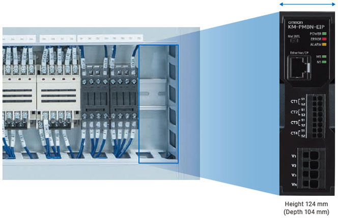
Achieves EtherNet/IP™ support in a slim body.Significant space savings allow Installation even in small gaps, whether for single or multiple circuits.
*1. As of July 2025, according to our research. For EtherNet/IP™ compatible models and systems measuring 400 V.

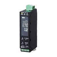
KM-PM
產品特色
38 mm-wide Ethernet Power Monitor for Global Control Panel Integration
[1. Easy to Install] Reduces Installation work inside panels
Can be installed even in the small open spaces of existing panels.

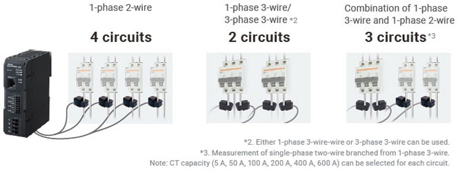
Compatible with multiple circuits, allowing minimization of wiring and equipment

Multi-circuit measurements reduces the measurement cost per circuit.
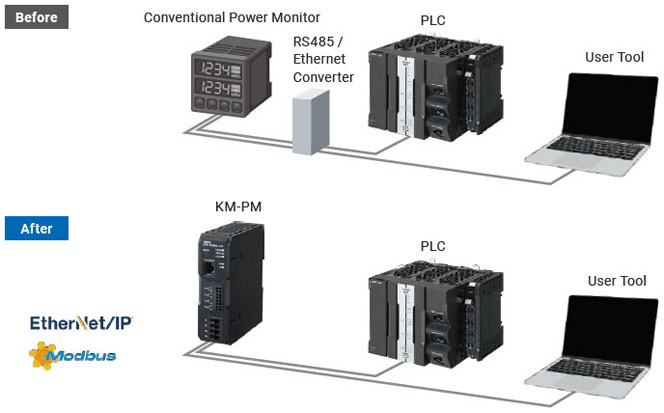
Equipped with Ethernet as a Standard Communication Interface ― No Converter Required, Reducing Wiring Effort

Compatible with Ethernet communication (EtherNet/IP™, ModbusTCP), improving connectivity to production equipment and user tools.
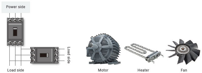
Its space-saving design enables measurement at the individual small breaker level.
Its space-saving, multi-circuit monitoring*4 allows measurement down to individual small breakers, providing detailed insight into power consumption in production equipment.
*4. Monitoring is only possible when both targets have the same voltage.
An additional unit is needed when using a different voltage.
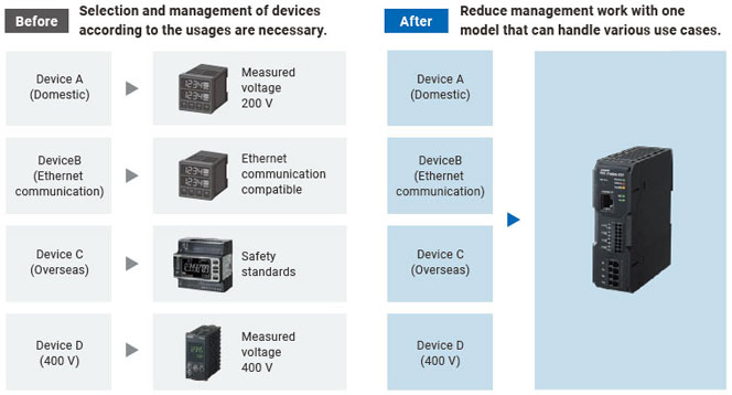
[2. Easy to Choose] Reducing the effort of model selection
Acquired major safety standards, enabling global export

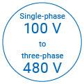
KM-PM supports single-phase 100 V to three-phase 480 V, enabling Power measurement for a wide range of equipment. Additionally, it has obtained major safety certifications, allowing for global deployment.
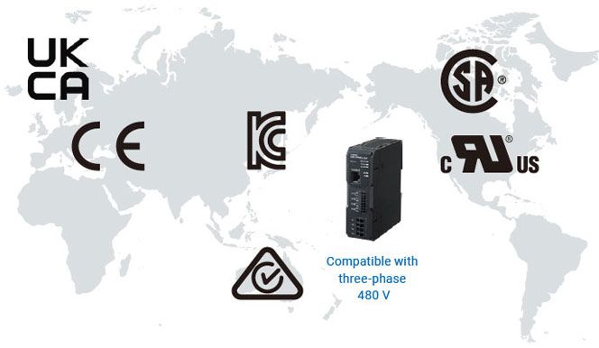
Compatible with a wide range of voltage environments to prevent model selection errors
Previously, selecting and managing devices for each machine and region was time-consuming. With just one KM-PM model, you can support diverse equipment worldwide―simplifying selection, reducing management workload, and promoting global standardization.
[3. Easy to Setup] Minimize System Setup and Configuration Time
Miswiring and incorrect settings occurred cause a significant amount of rework in system construction.With KM-PM, even users without expertise in power measurement can easily operate the system thanks to its intuitive UI design, significantly reducing rework.

For building green control panels
Natural disasters caused by global warming and climate change have become global social issue, that drives over 150 countries and regions worldwide to take action toward decarbonization.Our goal is to reduce greenhouse gas (GHG) emissions toward by half through new ways of building control panels, that key figure of the manufacturing site.

[Green] Creating green control panels
Reducing GHG emission of control panels to achieve carbon neutrality
This Value Design also integrate environment consideration concept that enable earth and user-friendly control panel building.
[Process] Innovation for design, building Process
Realize greatly reduces design/manufacturing work
eCAD library provided for all models greatly reduces design work. Push-In Plus technology requires only a single step, greatly reducing wiring work.
[Panel] Further Evolution for Panels
Realize compact & highly reliable control panels
Unified size and side-by-side mounting help delivering more compact control panels with additional functionality.OMRON Push-In Plus technology for easy wire insertion and firm wire holding ability.
[People] Simple & Easy People
Provide reliable and comfortable manufacturing for all people who deal with control panels
OMRON’s Push-In Plus technology is as easy as inserting to an earphone jack. This reduces the load on worker fingers.
Integrating green perspectives into Value Design

Value Design for Panel (Value Design) is the common concept shared across OMRON’s in-panel product specifications to deliver new value to your control panels.This Value Design also integrate environment consideration concept that enable earth and user-friendly control panel building.
Main Unit
| Rated input voltage (Shared power supply) | Model |
|---|---|
| 3-phase 4-wire: 100 to 277 VAC (L-N), 173 to 480 VAC (L-L) 1-phase 2-wire: 100 to 277 VAC 1-phase 3-wire: 100 to 240 VAC (L-N), 200 to 480 VAC (L-L) 3-phase 3-wire: 1 phase grounded: 100 to 480 VAC (L-L) 3-phase 3-wire: ungrounded: 173 to 480 VAC (L-L) |
KM-PMBN-EIP |
CT (order separately)
| Rated primary current | Model |
|---|---|
| 5 A | KM-PCBE005 |
| 50 A | KM-PCBE050 |
| 100 A | KM-PCBE100 |
| 200 A | KM-PCBE200 |
| 400 A | KM-PCBE400 |
| 600 A *1 *2 | KM-PCBE600 |
*1. KM-PCBE600 is only available in certain regions.
*2. The CT with a 600 A rating (KM-PCBE600) does not support safety standard certification, including UL/CSA certification.
EtherNet/IP communications cable recommended parts
Use a Category 5 or higher STP cable (shielded twisted pair cable).
Cable with Connectors
| Item | Recommended manufacturer |
Cable length (m) |
Model | |
|---|---|---|---|---|
| Wire Gauge and Number of Pairs: AWG26, 4-pair Cable Cable Sheath material: LSZH *2 |
Cable with Connectors on Both Ends (RJ45/RJ45) Standard RJ45 plug type *1 Cable color: Yellow *3  |
OMRON | 0.3 | XS6W-6LSZH8SS30CM-Y |
| 0.5 | XS6W-6LSZH8SS50CM-Y | |||
| 1 | XS6W-6LSZH8SS100CM-Y | |||
| 2 | XS6W-6LSZH8SS200CM-Y | |||
| 3 | XS6W-6LSZH8SS300CM-Y | |||
| 5 | XS6W-6LSZH8SS500CM-Y | |||
| Wire Gauge and Number of Pairs: AWG22, 2-pair Cable |
Cable with Connectors on Both Ends (RJ45/RJ45) Rugged RJ45 plug type *1 Cable color: Light blue  |
OMRON | 0.3 | XS5W-T421-AMD-K |
| 0.5 | XS5W-T421-BMD-K | |||
| 1 | XS5W-T421-CMD-K | |||
| 2 | XS5W-T421-DMD-K | |||
| 5 | XS5W-T421-GMD-K | |||
| 10 | XS5W-T421-JMD-K | |||
*1. Cables with standard RJ45 plugs are available in the following lengths: 0.2 m, 0.3 m, 0.5 m, 1 m, 1.5 m, 2 m, 3 m, 5 m, 7.5 m, 10 m, 15 m, 20 m.
Cables with rugged RJ45 plugs are available in the following lengths: 0.3 m, 0.5 m, 1 m, 2 m, 3 m, 5 m, 10 m, 15 m.
For details, refer to the Industrial Ethernet Connectors Catalog (Cat. No. G019).
*2. The lineup features Low Smoke Zero Halogen cables for in-cabinet use and PUR cables for out-of-cabinet use.
*3. Cable colors are available in yellow, green, and blue. The last character of the model changes to "-G" or "-B".
Connect to Condition Monitoring Configuration Too (Settling Tool), PLC, and PC using Ethernet cable.
Category 5 or higher STP (shielded twisted pair) cable is used.Either straight or cross cable can be used.
Cable/Connector
| Part name | Manufacturer | Model |
|---|---|---|
| Cable | Kuramo Electric Co. | KETH-SB * |
| RJ45 connector | Panduit Corporation | MPS588-C * |
* It is recommended to use the cable and connector in combination described above.
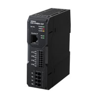
Industrial switching hub (recommended parts)
| Recommended manufacturer | Appearance | Functions | Number of ports | Model |
|---|---|---|---|---|
| OMRON |  |
Quality of Service (QoS): EtherNet/IP control data priority 10/100BASE-TX, Auto-Negotiation |
5 | W4S1-05D |
| Cisco Systems, Inc | Consult the manufacturer. https://www.cisco.com/ https://www.cisco.com/ |
|||
| Contec USA, Inc. | Consult the manufacturer.https://www.contec.com/us/ |
|||
| Phoenix Contact USA | Consult the manufacturer.https://www.phoenixcontact.com/online/portal/pc |
|||
Main unit
| Item | Function | |
|---|---|---|
| Input specifications |
Rated input voltage (Shared power supply) |
3-phase 4-wire: 100 to 277 VAC (L-N), 173 to 480 VAC (L-L) 1-phase 2-wire: 100 to 277 VAC 1-phase 3-wire: 100 to 240 VAC (L-N), 200 to 480 VAC (L-L) 3-phase 3-wire: 1 phase grounded: 100 to 480 VAC (L-L) 3-phase 3-wire: ungrounded: 173 to 480 VAC (L-L) |
| Input voltage fluctuation range |
85 to 115% of the rated input | |
| Connectable CT | Dedicated CT | |
| Rated input frequency | 50/60 Hz | |
| Applicable circuit type | 3-phase 4-wire, 1-phase 2-wire, 1-phase 3-wire, 3-phase 3-wire | |
| Number of measuring circuits |
3-phase 4-wire: 1 circuit at max. 1-phase 2-wire: 4 circuits at max. 1-phase 3-wire, 3-phase 3-wire: 2 circuits at max. |
|
| CT secondary side rated current |
According to the rating of dedicated CTs | |
| Maximum current for CT secondary side |
According to the rating of dedicated CTs | |
| Power consumption | 15 VA or less | |
| Ambient operating temperature | -25 to 55°C (with no condensation or icing) | |
| Ambient operating humidity | 25% to 85% RH | |
| Storage temperature | -25 to 85°C (with no condensation or icing) | |
| Storage humidity | 25% to 85% RH | |
| Dielectric strength voltage | 2,000 VAC for 1 minute Between (Voltage input terminals + Current input terminals) and LAN port Between electronic circuitry and case |
|
| Insulation resistance | 20 MΩ min (500 VDC mega) Between (Voltage input terminals + Current input terminals) and LAN port Between electronic circuitry and case |
|
| Vibration resistance | Single amplitude: 0.35 mm, Acceleration: 5m/s2, Frequency: 10 to 55 Hz 10 sweeps each in X, Y, and Z directions for 5 min |
|
| Shock resistance | 150m/s2, 3 times each in X, Y, and Z axes, 6 directions | |
| Display | LED | |
| Weight | 250 g | |
| Mounting method | DIN rail | |
| Altitude | 2,000 m or less | |
| Degree of protection | IP20 (excluding LAN port section) | |
| Electromagnetic environment | Industrial electromagnetic environment (EN/IEC 61326-1 Table 2) | |
| Applicable standards | CE, UKCA Installation environment: EN61010-1/EN61010-2-030, Pollution Degree 2, Overvoltage/measurement Category II (L-N: 480 V), III (L-N: 300 V) EMC: EN61326-1, ClassA (EMI), Industrial Location (EMS) UL •UL61010-1 Pollution degree 2, overvoltage Category II (L-N: 480 V), III (L-N: 300 V) •UL61010-2-030 Measurement Category II (L-N: 480 V) and III (L-N: 300 V) CSA •CAN/CSA C22.2 No.61010-1 Pollution degree 2, overvoltage Category II (L-N: 480 V), III (L-N: 300 V) •CAN/CSA C22.2 No.61010-2-030 Measurement Category II (L-N: 480 V) and III (L-N: 300 V) Korean Radio Law KSC9610-6-2, KSC9811 RCM EN61326-1 |
|
Measurements Specifications (50A CT, 100A CT, 200A CT, 400A CT, 600A CT *1 *2)
| Item | Description |
|---|---|
| Measurement item | Total power consumption (active, regenerative, and reactive), power (active and reactive), current, voltage, power factor, and frequency |
| Active power | 0.5% *3 (IEC62053-22 class 0.5S) *4 |
| Reactive power | 2% *3 (IEC62053-23 class2) *4 |
| Measurement frequency | 80 ms (50 Hz), 66.7 ms (60 Hz) |
| Functions | Conversion |
*1. KM-PCBE600 is only available in certain regions.
*2. The CT with a 600 A rating (KM-PCBE600) does not support safety standard certification, including UL/CSA certification.
*3. Errors from dedicated CT are not included.
*4. IEC62053 is an international standard on Power meters.
Measurement Specifications (5A CT)
| Item | Description | |
|---|---|---|
| Measurement item | Total power consumption (active, regenerative, and reactive), power (active and reactive), current, voltage, power factor, and frequency |
|
| Accuracy *1 *2 *3 |
Voltage *4 | ±0.5% of F.S. ±1 digit |
| Current *5 | ±0.5% of F.S. ±1 digit | |
| Power | ±1.0% of F.S. ±1 digit (Power factor = 1) | |
| Frequency | ±0.2% of F.S. ±1 digit | |
| Effect of temperature *6 | ±1.0% of F.S. | |
| Influence of frequency *7 | ±1.0% of F.S. | |
| Influence of harmonics *8 | ±0.5% of F.S. | |
| Measurement frequency | 80 ms (50 Hz), 66.7 ms (60 Hz) | |
| Functions | Conversion | |
*1. Errors from dedicated CT are not included.
*2. Value when ambient temperature of 23°C, rated input, and rated frequency.
*3. 10% or more of the rated input current.
*4. For the voltage between R and T phases, the accuracy is ±1.0% of F.S ±1 digit under the same conditions.
*5. For the S phase current of 3-phase 3-wire and N phase current of 1-wire 3-phase, the accuracy is ±1.0% of F.S ±1 digit under the same conditions.
*6. Percentage with respect to measurement value when within operating temperature range, ambient temperature of 23°C, rated input, rated frequency, and power factor of 1.
*7. Percentage with respect to measurement value when within range of rated frequency ±5 Hz, ambient temperature of 23°C, rated input, rated frequency, and power factor of 1.
*8. Error margin when ambient temperature of 23°C and superimposed the 2nd, 3rd, 5th, 7th, 9th, 11th, and 13th harmonics with content percentages of 30% current and 5% voltage relative to the fundamental wave.
Communications specifications
| Item | Description | |
|---|---|---|
| Communications protocols | TCP/IP, UDP/IP | |
| Supported services | MODBUS and TCP EtherNet/IP (Tag-Data-Link (Class1)), CIP message communications (Class3/UCMM) BOOTP (Client), DHCP (Client) ACD LLDP (Agent: Send Functions only) |
|
| Number of ports | 1 | |
| Physical layer | 100BASE-TX | |
| Ethernet interface | AutoNegotiation, AutoMDI/MDI-X | |
| Transmission specifications |
Media access method | CSMA/CD |
| Modulation | Baseband | |
| Topology | Star | |
| Baud rate | 100 Mbps (100BASE-TX) | |
| Transmission media | Twisted-pair cable (Shielded: STP) Category 5, 5e or more | |
| Transmission distance | Up to 100 m (Distance between hub and node) | |
| Number of cascade connections |
No restrictions in the use of Switching hub. | |
Dedicated CT specifications
| Model | KM-PCBE005 | KM- PCBE050 | KM- PCBE100 | KM- PCBE200 | KM- PCBE400 | KM- PCBE600 *1 *2 |
|
|---|---|---|---|---|---|---|---|
| Primary side rated current | 5 A | 50 A | 100 A | 200 A | 400 A | 600 A | |
| Rated voltage | 480 VAC | ||||||
| Secondary winding | 3,000 turns | 6,000 turns | 9,000 turns | ||||
| Insulation resistance | Between output terminals and case: 50 mΩ min. | ||||||
| Dielectric strength voltage | Between Output terminals and case: 2,000 VAC for 1 minutes | ||||||
| Protective element | 7.5 V clamp element | ||||||
| Allowable number of attachments and detachments |
100 times | ||||||
| Diameter of wire attachable | 7.9 mm dia. max. |
9.5 mm dia. max. |
14.5 mm dia. max. |
24.0 mm dia. max. |
35.5 mm dia. max. | ||
| Operating temperature and humidity ranges |
-25 to 55°C, 25% to 85% RH (with no icing or condensation) | ||||||
| Storage temperature and humidity ranges |
-30 to 65°C, 25% to 85% RH (with no icing or condensation) | ||||||
| Supplied cable length | 2.9 m | ||||||
| Supplied cable terminals |
Output | Ferrule terminal | |||||
| CT | Round terminal | ||||||
Note: 1. When using the CT as a set with the KM-PMBN-EIP Power Monitor, also consider the operating environment conditions of the power monitor. Consider the operating environment conditions of the device that is used as a set with this CT.
*1. KM-PCBE600 is only available in certain regions.
*2. The CT with a 600 A rating (KM-PCBE600) does not support safety standard certification, including UL/CSA certification.
(單位:mm)
Main unit
KM-PMBN-EIP

Dedicated CT
KM-PCBE005

KM-PCBE050

KM-PCBE100

KM-PCBE200

KM-PCBE400
KM-PCBE600

Note: 1. KM-PCBE600 is only available in certain regions.
Note: 2. The CT with a 600 A rating (KM-PCBE600) does not support safety standard certification, including UL/CSA certification.
CT-supplied cable

Note: The CT-supplied cable is attached to the CT.
Optional Products for DIN Track Mounting
DIN Tracks
PFP-100N
PFP-50N

End Plate
PFP-M

English
Global Edition
| Catalog Name | Catalog Number [size] |
Last Update | |
|---|---|---|---|
| N243-E1-01 [6837KB] |
Oct 01, 2025
20251001
|
KM-PM Catalog | |
| Y235-E1-09 [5816KB] |
Oct 20, 2025
20251020
|
Panel Solution-Value Design for Panel |
如有需要請洽各所營業人員
誠睿台南所 TEL:06-2493086
誠睿台中所 TEL:04-23380790
誠睿新竹所 TEL:03-6685558
客服信箱 service@hitifa.com.tw
誠睿台南所 TEL:06-2493086
誠睿台中所 TEL:04-23380790
誠睿新竹所 TEL:03-6685558
客服信箱 service@hitifa.com.tw
如有需要請洽各所營業人員
誠睿台南所 TEL:06-2493086
誠睿台中所 TEL:04-23380790
誠睿新竹所 TEL:03-6685558
客服信箱 service@hitifa.com.tw
誠睿台南所 TEL:06-2493086
誠睿台中所 TEL:04-23380790
誠睿新竹所 TEL:03-6685558
客服信箱 service@hitifa.com.tw