Control Panels: The Heart of Manufacturing Sites.
Evolution in control panels results in large evolution in production facilities.
And if control panel design, control panel manufacturing processes, and human interaction with them are innovated, control panel manufacturing becomes simpler and takes a leap forward.
OMRON will continue to achieve a control panel evolution and process innovation through many undertakings starting with the shared Value Design for Panel *1 concept for the specifications of products used in control panels.

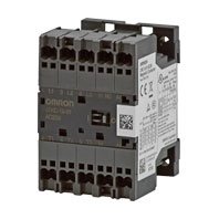
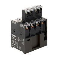
J7KC Series
產品特色
Best Match for upto 2.2 kW (240 VAC) *, 5.5 kW (440 VAC) Motor and Primary Side switches * Based on JIS C 8201-4-1
New Value For Control Panels
*1 Value Design for Panel

Our shared Value Design for Panel (herein after referred to as "Value Design") concept for the specifications of products used in control panels will create new value to our customer’s control panels.
Combining multiple products that share the Value Design concept will further increase the value provided to control panels.
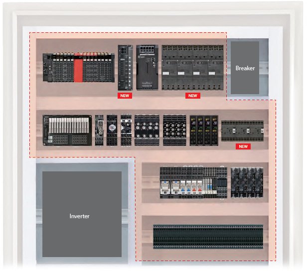
Finally Low Voltage Switching Gears joining into the OMRON’s Panel Solution portfolio
A wide product lineup of Control Panel Solution that cover even motor control contributes to TCO*1 reduction in control panel manufacturing.
*1. TCO: Total Cost of Ownership. Total cost from control panel design / production to operation / maintenance.
Main Features of Value Design

To further improve control panels with newly added Low Voltage Switch Gears for motor control
Best match for a motor drive (AC3 Class) and a primary side of drive control equipment
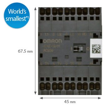
Compact
The widths of all series models are unified to 45 mm.
Compactly mountable in a control panel
Conform to Main Safety Standards

Mirror contact mechanism
Supports safety applications
High endurance
One million times or more of electrical endurance*2
*1. Based on June 2019 OMRON investigation. On the Push-In models.
*2. Shutting off by thermal overload relay is excluded.
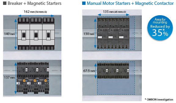
Space-saving design helps downsize control panels.
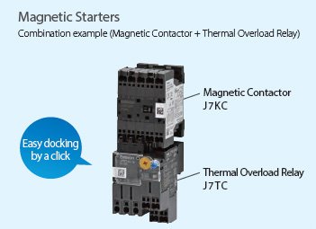
Total solution for motor applications
New lineup of ON/OFF controllable Low Voltage Switching Gears supports total motor application, in addition to inverters and servos
PCB assembly production line

Model Number Structure
Model Number Legend
Order according to the format described in Ordering Information.
Ordering Information
Main unit
| Product Type | Operation | Coil rating | Auxiliary contact | Model |
|---|---|---|---|---|
| Magnetic contactor | AC-operated | 24 VAC | SPST-1NO | J7KC-12-10 AC24 |
| SPST-1NC | J7KC-12-01 AC24 | |||
| 48 VAC | SPST-1NO | J7KC-12-10 AC48 | ||
| SPST-1NC | J7KC-12-01 AC48 | |||
| 100 VAC | SPST-1NO | J7KC-12-10 AC100 | ||
| SPST-1NC | J7KC-12-01 AC100 | |||
| 110 VAC | SPST-1NO | J7KC-12-10 AC110 | ||
| SPST-1NC | J7KC-12-01 AC110 | |||
| 120 VAC | SPST-1NO | J7KC-12-10 AC120 | ||
| SPST-1NC | J7KC-12-01 AC120 | |||
| 200 VAC | SPST-1NO | J7KC-12-10 AC200 | ||
| SPST-1NC | J7KC-12-01 AC200 | |||
| 220 VAC | SPST-1NO | J7KC-12-10 AC220 | ||
| SPST-1NC | J7KC-12-01 AC220 | |||
| 230 VAC | SPST-1NO | J7KC-12-10 AC230 | ||
| SPST-1NC | J7KC-12-01 AC230 | |||
| 240 VAC | SPST-1NO | J7KC-12-10 AC240 | ||
| SPST-1NC | J7KC-12-01 AC240 | |||
| 380 VAC | SPST-1NO | J7KC-12-10 AC380 | ||
| SPST-1NC | J7KC-12-01 AC380 | |||
| 400 VAC | SPST-1NO | J7KC-12-10 AC400 | ||
| SPST-1NC | J7KC-12-01 AC400 | |||
| 440 VAC | SPST-1NO | J7KC-12-10 AC440 | ||
| SPST-1NC | J7KC-12-01 AC440 | |||
| 500 VAC | SPST-1NO | J7KC-12-10 AC500 | ||
| SPST-1NC | J7KC-12-01 AC500 | |||
| DC-operated (With built-in surge absorption uni) |
12 VDC | SPST-1NO | J7KC-12-10 DC12 | |
| SPST-1NC | J7KC-12-01 DC12 | |||
| 24 VDC | SPST-1NO | J7KC-12-10 DC24 | ||
| SPST-1NC | J7KC-12-01 DC24 | |||
| 48 VDC | SPST-1NO | J7KC-12-10 DC48 | ||
| SPST-1NC | J7KC-12-01 DC48 | |||
| 60 VDC | SPST-1NO | J7KC-12-10 DC60 | ||
| SPST-1NC | J7KC-12-01 DC60 | |||
| 100 VDC | SPST-1NO | J7KC-12-10 DC100 | ||
| SPST-1NC | J7KC-12-01 DC100 | |||
| 110 VDC | SPST-1NO | J7KC-12-10 DC110 | ||
| SPST-1NC | J7KC-12-01 DC110 | |||
| 120 VDC | SPST-1NO | J7KC-12-10 DC120 | ||
| SPST-1NC | J7KC-12-01 DC120 | |||
| 200 VDC | SPST-1NO | J7KC-12-10 DC200 | ||
| SPST-1NC | J7KC-12-01 DC200 | |||
| 210 VDC | SPST-1NO | J7KC-12-10 DC210 | ||
| SPST-1NC | J7KC-12-01 DC210 | |||
| 220 VDC | SPST-1NO | J7KC-12-10 DC220 | ||
| SPST-1NC | J7KC-12-01 DC220 | |||
| Reversing magnetic contactor |
AC-operated | 24 VAC | SPST-1NO | J7KCR-12-10 AC24 |
| SPST-1NC | J7KCR-12-01 AC24 | |||
| 48 VAC | SPST-1NO | J7KCR-12-10 AC48 | ||
| SPST-1NC | J7KCR-12-01 AC48 | |||
| 100 VAC | SPST-1NO | J7KCR-12-10 AC100 | ||
| SPST-1NC | J7KCR-12-01 AC100 | |||
| 110 VAC | SPST-1NO | J7KCR-12-10 AC110 | ||
| SPST-1NC | J7KCR-12-01 AC110 | |||
| 120 VAC | SPST-1NO | J7KCR-12-10 AC120 | ||
| SPST-1NC | J7KCR-12-01 AC120 | |||
| 200 VAC | SPST-1NO | J7KCR-12-10 AC200 | ||
| SPST-1NC | J7KCR-12-01 AC200 | |||
| 220 VAC | SPST-1NO | J7KCR-12-10 AC220 | ||
| SPST-1NC | J7KCR-12-01 AC220 | |||
| 230 VAC | SPST-1NO | J7KCR-12-10 AC230 | ||
| SPST-1NC | J7KCR-12-01 AC230 | |||
| 240 VAC | SPST-1NO | J7KCR-12-10 AC240 | ||
| SPST-1NC | J7KCR-12-01 AC240 | |||
| 380 VAC | SPST-1NO | J7KCR-12-10 AC380 | ||
| SPST-1NC | J7KCR-12-01 AC380 | |||
| 400 VAC | SPST-1NO | J7KCR-12-10 AC400 | ||
| SPST-1NC | J7KCR-12-01 AC400 | |||
| 440 VAC | SPST-1NO | J7KCR-12-10 AC440 | ||
| SPST-1NC | J7KCR-12-01 AC440 | |||
| 500 VAC | SPST-1NO | J7KCR-12-10 AC500 | ||
| SPST-1NC | J7KCR-12-01 AC500 | |||
| DC-operated (With built-in surge absorption unit) |
12 VDC | SPST-1NO | J7KCR-12-10 DC12 | |
| SPST-1NC | J7KCR-12-01 DC12 | |||
| 24 VDC | SPST-1NO | J7KCR-12-10 DC24 | ||
| SPST-1NC | J7KCR-12-01 DC24 | |||
| 48 VDC | SPST-1NO | J7KCR-12-10 DC48 | ||
| SPST-1NC | J7KCR-12-01 DC48 | |||
| 60 VDC | SPST-1NO | J7KCR-12-10 DC60 | ||
| SPST-1NC | J7KCR-12-01 DC60 | |||
| 100 VDC | SPST-1NO | J7KCR-12-10 DC100 | ||
| SPST-1NC | J7KCR-12-01 DC100 | |||
| 110 VDC | SPST-1NO | J7KCR-12-10 DC110 | ||
| SPST-1NC | J7KCR-12-01 DC110 | |||
| 120 VDC | SPST-1NO | J7KCR-12-10 DC120 | ||
| SPST-1NC | J7KCR-12-01 DC120 | |||
| 200 VDC | SPST-1NO | J7KCR-12-10 DC200 | ||
| SPST-1NC | J7KCR-12-01 DC200 | |||
| 210 VDC | SPST-1NO | J7KCR-12-10 DC210 | ||
| SPST-1NC | J7KCR-12-01 DC210 | |||
| 220 VDC | SPST-1NO | J7KCR-12-10 DC220 | ||
| SPST-1NC | J7KCR-12-01 DC220 |
Options (Order Separately)
Auxiliary contact unit
| Number of poles | Auxiliary contact | Model |
|---|---|---|
| 2 poles | 2PST-2NO | J73KC-AM-20 |
| 2PST-1NO 1NC | J73KC-AM-11 | |
| 2PST-2NC | J73KC-AM-02 | |
| 4 poles | 4PST-4NO | J73KC-AM-40 |
| 4PST-3NO 1NC | J73KC-AM-31 | |
| 4PST-2NO 2NC | J73KC-AM-22 | |
| 4PST-1NO 3NC | J73KC-AM-13 | |
| 4PST-4NC | J73KC-AM-04 |
Interlock unit
| Model |
|---|
| J74KC-A |
Reversing conductor kit
| Type | Model |
|---|---|
| For main circuit | J75KC-WKR-A |
| For auxiliary circuit | J75KC-WKR-B |
Coil surge absorption unit
| Adopted Coil voltage type | LED indicator | Model |
|---|---|---|
| 24-48 VAC | No | J76KC-RC-1 |
| 48-125 VAC | J76KC-RC-2 | |
| 100-250 VAC | J76KC-RC-3 | |
| 24-48 VAC | Yes | J76KC-RC-N-1 |
| 48-125 VAC | J76KC-RC-N-2 |
Insulation stop
| Model | Minimum order (bag) |
|---|---|
| J77KC-K | 1 (30 pcs./bag) |
Tools for removal
| Model |
|---|
| J78KC |
DIN Rails (Order Separately)
Mounting Rail
| Model |
|---|
| PFP-100N |
| PFP-50N |
Mounting Rail
| Model |
|---|
| PFP-100N2 |
End Plate
| Model |
|---|
| PFP-M |
Spacer
| Model |
|---|
| PFP-S |
Note:
1. Order the DIN Rails (Order Separately) in units of ten.
2. Rails conform to DIN standards.
The ratings/specifications are the same for both non-reversing/reversing types.
Coil rating
AC operated
| Displayed model |
Rated voltage | Allowable voltage range | Must operate voltage |
Must release voltage |
|||
|---|---|---|---|---|---|---|---|
| 50 Hz | 60 Hz | 50 Hz | 60 Hz | ||||
| AC 24 | 24 VAC | 24-26 VAC | 85 to 110% | 21-27 VAC | 21-29 VAC | 85% max. | 20% min. |
| AC 48 | 48 VAC | 48-52 VAC | 41-53 VAC | 41-58 VAC | |||
| AC 100 | 100 VAC | 100-110 VAC | 85-110 VAC | 85-121 VAC | |||
| AC 110 | 100-110 VAC | 110-120 VAC | 85-121 VAC | 94-132 VAC | |||
| AC 120 | 110-120 VAC | 120-130 VAC | 94-132 VAC | 102-143 VAC | |||
| AC 200 | 200 VAC | 200-220 VAC | 170-220 VAC | 170-242 VAC | |||
| AC 220 | 200-220 VAC | 220-240 VAC | 170-242 VAC | 187-264 VAC | |||
| AC 230 | 220-230 VAC | 230 VAC | 187-253 VAC | 196-253 VAC | |||
| AC 240 | 220-240 VAC | 240-260 VAC | 187-264 VAC | 204-286 VAC | |||
| AC 380 | 346-380 VAC | 380-420 VAC | 295-418 VAC | 323-462 VAC | |||
| AC 400 | 380-400 VAC | 400-440 VAC | 323-440 VAC | 340-484 VAC | |||
| AC 440 | 415-440 VAC | 440-480 VAC | 353-484 VAC | 374-528 VAC | |||
| AC 500 | 480-500 VAC | 500-550 VAC | 408-550 VAC | 425-605 VAC | |||
DC operated
| Displayed model |
Rated voltage | Allowable voltage range | Must operate voltage |
Must release voltage |
|
|---|---|---|---|---|---|
| DC 12 | 12 VDC | 85 to 110% | 11-14 VDC | 85% max. | 10% min. |
| DC 24 | 24 VDC | 21-27 VDC | |||
| DC 48 | 48 VDC | 41-53 VDC | |||
| DC 60 | 60 VDC | 51-66 VDC | |||
| DC 100 | 100 VDC | 85-110 VDC | |||
| DC 110 | 110 VDC | 94-121 VDC | |||
| DC 120 | 120 VDC | 102-132 VDC | |||
| DC 200 | 200 VDC | 170-220 VDC | |||
| DC 210 | 210 VDC | 179-231 VDC | |||
| DC 220 | 220 VDC | 187-242 VDC | |||
Coil characteristics (reference value)
AC operated
| Frequency | 50 Hz | 60 Hz | |
|---|---|---|---|
| Coil power consumption |
Making (VA) | 22 (200 V) | 25 (220 V) |
| Holding (VA) | 4.5 (200 V) | 4.5 (220 V) | |
| Power loss (W) | 1.2 (200 V) | 1.3 (220 V) | |
| Must operate voltage (V) | 122 to 135 | 128 to 138 | |
| Must release voltage (V) | 80 to 89 | 83 to 96 | |
| Operate time (ms) | 17 to 26 | ||
| Release time (ms) | 6 to 16 | ||
Note:
1. Coil ratings: Characteristics for 200 VAC, 50 Hz / 200-220 VAC, 60 Hz
2. Coil power consumption value is the same for a coil that is not rated 200 VAC.
3. Indicated operate/release times for 200 VAC, 50 Hz.
4. Closed and open voltages of 100 V coil (100 VAC, 50 Hz/100-110 VAC, 60 Hz) are approximately one half the values in the table above.
5. Values in the table above are examples for 20°C cold condition.
DC operated
| Coil power consumption |
Making (W) | 2.4 (24 V) |
|---|---|---|
| Holding (W) | 2.2 (24 V) | |
| Time constant (ms) | Holding | 20 |
| Must operate voltage (V) | 10 to 11 | |
| Must release voltage (V) | 4 to 6 | |
| Operate time (ms) | 34 to 60 | |
| Release time (ms) | 5 to 10 | |
Note:
1. Coil ratings: Characteristics for 24 VDC
2. Coil power consumption value is the same for a coil that is not rated 24 VDC.
3. Values in the table above are examples for 20°C cold condition.
Ratings/Characteristics
| Main circuit rating |
Rating based on IEC 60947-4-1 |
AC-1 (Resistive load) |
Voltage range (V) | AC200-240 AC | AC380-440 AC | |||||||||||
|---|---|---|---|---|---|---|---|---|---|---|---|---|---|---|---|---|
| Rated operational current (A) | 15 | 15 | ||||||||||||||
| AC-3 (3-phase cage motor) |
Voltage range (V) | 200-240 AC | 380-440 AC | 500-550 AC | 600-690 AC | |||||||||||
| Rated capacity (kW) | 3 | 5.5 | 5.5 | 4 | ||||||||||||
| Rated operational current (A) | 12 | 12 | 9 | 5 | ||||||||||||
| AC-4 (3-phase cage motor) |
Voltage range (V) | 200-240 AC | 380-440 AC | 500-550 AC | 600-690 AC | |||||||||||
| Rated capacity (kW) | 3 | 5.5 | 5.5 | 4 | ||||||||||||
| Rated operational current (A) | 12 | 12 | 9 | 5 | ||||||||||||
| DC-1 (Resistive load L/R ≤ 1 ms) |
Voltage range (V) | 24 DC | 48 DC | 110 DC | 220 DC | |||||||||||
| Rated operational current (A) |
Number of serial contacts 1 | 12 | 12 | 3 | 0.7 | |||||||||||
| Number of serial contacts 2 | 12 | 12 | 9 | 4 | ||||||||||||
| Number of serial contacts 3 | 12 | 12 | 12 | 12 | ||||||||||||
| DC-3, DC-5 (DC motor load L/R ≤ 15 ms) |
Voltage range (V) | 24 DC | 48 DC | 110 DC | 220 DC | |||||||||||
| Rated operational current (A) |
Number of serial contacts 1 | 2 | 1.5 | 1 | 0.1 | |||||||||||
| Number of serial contacts 2 | 10 | 3 | 0.85 | 0.35 | ||||||||||||
| Number of serial contacts 3 | 12 | 6 | 1.7 | 0.7 | ||||||||||||
| Conventional free air thermal current (rated flowing current) (A) |
15 | |||||||||||||||
| Rating based on UL 60947-4-1, CSA C22.2 |
3-phase motor | Voltage range (V) | 200 AC | 220-240 AC | 440-480 AC | 550-600 AC | ||||||||||
| Rated capacity (HP) | 3 | 3 | 5 | 5 | ||||||||||||
| Rated operational current (A) | 11 | 9.6 | 7.6 | 6.1 | ||||||||||||
| Rated current (A) | 15 | |||||||||||||||
| Single-phase motor |
Voltage range (V) | 110-120 AC | 200 AC | 220-240 AC | ||||||||||||
| Rated capacity (HP) | 3/4 | 1-1/2 | 2 | |||||||||||||
| Rated operational current (A) | 13.8 | 11.5 | 12 | |||||||||||||
| Rated current (A) | 15 | |||||||||||||||
| FUSE | 30A (Class K5, RK5) | |||||||||||||||
| Rating based on JIS C 8201-4-1 |
AC-1 (resistive load) |
Voltage range (V) | 200-240 AC | 380-440 AC | ||||||||||||
| Rated operational current (A) | 15 | 15 | ||||||||||||||
| AC-3 (3-phase cage motor) |
Voltage range (V) | 200-240 AC | 380-440 AC | 500-550 AC | ||||||||||||
| Rated capacity (kW) | 2.2 | 5.5 | 5.5 | |||||||||||||
| Rated operational current (A) | 12 | 12 | 9 | |||||||||||||
| DC-1 (Resistive load L/R ≤ 1 ms) |
Voltage range (V) | 24 DC | 48 DC | 110 DC | 220 DC | |||||||||||
| Rated operational current (A) |
Number of serial contacts 1 | 12 | 12 | 3 | 0.7 | |||||||||||
| Number of serial contacts 2 | 12 | 12 | 9 | 4 | ||||||||||||
| Number of serial contacts 3 | 12 | 12 | 12 | 12 | ||||||||||||
| DC-3, DC-5 (DC motor load L/R ≤ 15 ms) |
Voltage range (V) | 24 DC | 48 DC | 110 DC | 220 DC | |||||||||||
| Rated operational current (A) |
Number of serial contacts 1 | 2 | 1.5 | 1 | 0.1 | |||||||||||
| Number of serial contacts 2 | 10 | 3 | 0.85 | 0.35 | ||||||||||||
| Number of serial contacts 3 | 12 | 6 | 1.7 | 0.7 | ||||||||||||
| Conventional free air thermal current (rated flowing current) (A) |
15 | |||||||||||||||
| Minimum operate voltage/current (reference value) | 24 VDC 10 mA | |||||||||||||||
| Electrical/ mechanical endurance |
Voltage range (V) | 220 AC | 440 AC | |||||||||||||
| Rated operational current (A) | 12 | 12 | ||||||||||||||
| Contact closed current (A) | 144 | 144 | ||||||||||||||
| Breaking current (A) | 120 | 120 | ||||||||||||||
| Switching frequency (times per hour) | 1800 | 1800 | ||||||||||||||
| Endurance (10,000 operations min.) |
Mechanical | 1000 | 1000 | |||||||||||||
| Electrical (AC3) | 100 *1 | |||||||||||||||
| Contact resistance (reference value) | 10 mΩ max. (6 VDC, 1 mA, voltage drop method) | |||||||||||||||
| Auxiliary circuit rating |
Rating based on IEC 60947-5-1/ JIS C 8201-5-1 |
Voltage range (V) | 100-120 AC |
200-240 AC |
380-440 AC |
500-600 AC |
24 DC | 48 DC | 110 DC | 220 DC | ||||||
| Rated operational current (A) | AC-15 (coil load) | DC-13 (coil load) | ||||||||||||||
| 3 | 3 | 1 | 0.5 | 2 | 1 | 0.3 | 0.2 | |||||||||
| AC-12 (resistive load) | DC-12 (resistive load) | |||||||||||||||
| 6 | 6 | 6 | 3 | 3 | 2 | 1.5 | 0.5 | |||||||||
| Contact closed and breaking current (A) | 30 | 30 | 10 | 5 | 30 | 30 | 10 | 5 | ||||||||
| Conventional free air thermal current (rated flowing current) (A) |
10 | |||||||||||||||
| Rating based on UL 508 |
Rated carry current (A) | 10 | 2.5 | |||||||||||||
| Voltage range (V) | 120 AC | 240 AC | 480 AC | 600 AC | 125 DC | 250 DC | ||||||||||
| Contact closed current (A) | 60 | 30 | 15 | 12 | 0.55 | 0.27 | ||||||||||
| Breaking current (A) | 6 | 3 | 1.5 | 1.2 | 0.55 | 0.27 | ||||||||||
| Rating code | A 600 | Q 300 | ||||||||||||||
| Minimum operate voltage/current (reference value) | 3 mA at 5 VDC | |||||||||||||||
| Electrical/ mechanical endurance |
Switching frequency (times per hour) | 1800 | ||||||||||||||
| Mechanical (10,000 cycles min.) | 1000 | |||||||||||||||
| Electrical (10,000 cycles min.) |
AC-15 | 220 V | 50 | |||||||||||||
| 440 V | 50 | |||||||||||||||
| AC-12 | 220 V | 25 | ||||||||||||||
| 440 V | 25 | |||||||||||||||
| DC-13 | 220 V | 15 | ||||||||||||||
| DC-12 | 220 V | 50 | ||||||||||||||
| Contact resistance (reference value) | 50 mΩ max. (6 VDC, 1 mA, voltage drop method) | |||||||||||||||
| Rated insulation voltage | 690 VAC | |||||||||||||||
| Rated impulse dielectric strength | 6 kV | |||||||||||||||
| Rated frequency | 50/60 Hz | |||||||||||||||
| Vibration resistance | Vibration: 10 to 55 Hz, acceleration: 15 m/s2 | |||||||||||||||
| Shock resistance | Shock value 50 m/s2 | |||||||||||||||
| Contact form | Double break form (main circuit: single contacts, auxiliary circuit: bifurcated contacts) | |||||||||||||||
| Contact material | Ag alloy | |||||||||||||||
| Mirror contact | Available *2 | |||||||||||||||
| Degree of protection | IP20 (IEC60529) | |||||||||||||||
| Operating temperature | -10 to +55°C (however, daily average shall not exceed 35°C) | |||||||||||||||
| Ambient storage temperature | -40 to +65°C (no condensation or icing) | |||||||||||||||
| Relative humidity | 45% to 85% RH (no condensation or icing) | |||||||||||||||
| Altitude | 2000 m max. | |||||||||||||||
| Weight | 160 g (J7KC-[]-AC)/190 g (J7KC-[]-DC)/400 g (J7KCR-[]-AC)/460 g (J7KCR-[]-DC) | |||||||||||||||
| Applicable Standards | Safety standard | EN 60947-4-1(IEC 60947-4-1), UL 60947-4-1, CSA 22.2 No.60947-4-1, CCC GB/T14048.4, UKCA |
||||||||||||||
*1. The electrical endurance is the value at 200 V based on the electrical endurance test conditions assumed in the IEC/JIS standards, and will vary depending on the characteristics and load conditions of the motor you use. A large motor starting current may cause a decrease of electrical endurance or contact sticking.
*2. A mirror contact is a mechanism found mainly in contactors.
With the combination of the main circuit and the auxiliary circuit of the main unit, welding the main contacts will result in a structure that secures a shock resistance voltage of 2.5 kV or more, or a contact interval of 0.5 mm or more, for all of the auxiliary circuit NC contacts even if the excitation of the coil is released. The main contact may turn on even if the auxiliary circuit is welded. Even with the combined usage of the auxiliary contact unit (J73KC-AM), welding the main contact in the main unit will create a mirror contact surface where the attached auxiliary contact (NC contact) is separated.
Options (Order Separately)
Auxiliary contact unit
J73KC
| Conventional free air thermal current (rated flowing current) [A] |
Contact closed and Breaking current [A] |
AC | DC | Minimum operate voltage/ current |
||||
|---|---|---|---|---|---|---|---|---|
| Operating voltage [V] |
Rated operational current (A) |
Operating voltage [V] |
Rated operational current (A) |
|||||
| Coil load (AC-15) |
Resistive load (AC-12) |
Coil load (DC-13) |
Resistive load (DC-12) |
|||||
| 10 | 30 | 100 to 120 AC | 3 | 6 | 24 DC | 2 | 3 | 5 VDC, 3 mA |
| 30 | 200 to 240 AC | 3 | 6 | 48 DC | 1 | 2 | ||
| 10 | 380 to 440 AC | 1 | 6 | 110 DC | 0.3 | 1.5 | ||
| 5 | 500 to 600 AC | 0.5 | 3 | 220 DC | 0.2 | 0.5 | ||
Coil surge absorption unit
| Model | Surge absorber |
Varistor voltage |
LED indicator |
Applicable model | Control circuit voltage | ||
|---|---|---|---|---|---|---|---|
| AC operated | DC operated | AC | DC | ||||
| J76KC-RC-1 | Varistor | 100 V | --- | J7KC-[]-AC | --- | 24-48 VAC | Not required * |
| J76KC-RC-2 | 240 V | 48-125 VAC | |||||
| J76KC-RC-3 | 470 V | 100-250 VAC | |||||
| J76KC-RC-N-1 | 100 V | LED (red) | 24-48 VAC | ||||
| J76KC-RC-N-2 | 240 V | 48-125 VAC | |||||
* The DC operated (J7KC-[]-DC) has a varistor built into the main unit.
(單位:mm)
Main unit
Magnetic contactor
J7KC
Reversing magnetic contactor
J7KCR
Options (Order Separately)
Auxiliary contact unit
J73KC
Interlock unit
J74KC
Reversing conductor kit
J75KC-WKR-A
J75KC-WKR-B
Coil surge absorption unit
J76KC-RC
J76KC-RC-N
Insulation stop
J77KC-K
Tools for removal
J78KC
DIN Rails (Order Separately)
Mounting Rail
PFP-100N
PFP-50N
Mounting Rail
PFP-100N2
End Plate
PFP-M
Spacer
PFP-S
English
Global Edition
| Catalog Name | Catalog Number [size] |
Last Update | |
|---|---|---|---|
| J229-E1-01 [2716KB] |
Dec 12, 2019
20191212
|
Low Voltage Switching Gears Catalog | |
| J230-E1-04 [6213KB] |
Jun 20, 2022
20220620
|
J7KC Series Data Sheet | |
| Y235-E1-01 [5944KB] |
Jul 19, 2022
20220719
|
Value Design for Panel Catalog |
如有需要請洽各所營業人員
誠睿台南所 TEL:06-2493086
誠睿台中所 TEL:04-23380790
誠睿新竹所 TEL:03-6685558
客服信箱 service@hitifa.com.tw
誠睿台南所 TEL:06-2493086
誠睿台中所 TEL:04-23380790
誠睿新竹所 TEL:03-6685558
客服信箱 service@hitifa.com.tw
如有需要請洽各所營業人員
誠睿台南所 TEL:06-2493086
誠睿台中所 TEL:04-23380790
誠睿新竹所 TEL:03-6685558
客服信箱 service@hitifa.com.tw
誠睿台南所 TEL:06-2493086
誠睿台中所 TEL:04-23380790
誠睿新竹所 TEL:03-6685558
客服信箱 service@hitifa.com.tw