商品搜尋
商品搜尋
行業別
功能
Banner

產品&服務

HITI Industrial Automation

G5RL

G5RL

產品特色
Low-profile Relay with Various Models

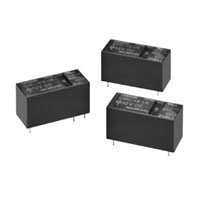
• Low profile: 15.7 mm in height.

• Creepage distance 8mm between coil and contacts

• 10 kV Impulse withstand voltage

• Models with AC coil available.

• High-Inrush model available (Inrush peak currents up to 100 A)

• Low Noise models available (Approx. 10 to 20 dB less sound pressure than standard G5RL-Series Relays)

• TV8 Rating models available (TV8 for UL standard)

Classi-
fication
Terminal
Shape
Contact
form
Enclosure
rating
Model Rated coil voltage Minimum
packing
unit
Standard PCB
terminals
SPST-NO
(1a)
Flux
protection
G5RL-1A-LN 5VDC, 12VDC, 24VDC 100 pcs/
tray
G5RL-1A-TV8 5VDC, 12VDC, 24VDC, 48VDC
High-
capacity
G5RL-1A-E-HR 5VDC, 12VDC, 24VDC, 48VDC
G5RL-1A-E-LN 5VDC, 12VDC, 24VDC
G5RL-1A-E-TV8 5VDC, 12VDC, 24VDC, 48VDC
SPDT (1c) G5RL-1-E 24VAC, 100VAC, 115VAC/120VAC,
200VAC, 230VAC/240VAC
G5RL-1-E-HR 5VDC, 12VDC, 24VDC, 48VDC

Note. When ordering, add the rated coil voltage to the model number.

G5RL 種類 2

However, the notation of the coil voltage on the product case as well as on the packing will be marked as [][] VDC.

Ratings

Coil

Low Noise Models: G5RL-1A(-E)-LN

Rated Voltage
(VDC)
Rated
current
(mA)
Coil
resistance
(Ω)
Must operate
voltage (V)
Must release
voltage (V)
Max. voltage
(V)
Power
consumption
(mW)
% of rated voltage
5 106 47.2 70% max. 10% min. 110% Approx. 530
12 44.2 272
24 22.1 1,086

Note 1. The rated current and coil resistance are measured at a coil temperature of 23°C with a tolerance of ±10%.
2. Be sure to use a diode for surge absorption for the coil.
3. The operating characteristics are measured at a coil temperature of 23°C.
4. The “Max. voltage” is the maximum voltage that can be applied to the relay coil.

High-Inrush Models: G5RL-1(A)-E-HR, G5RL-1A(-E)-TV8

Rated Voltage
(VDC)
Rated
current
(mA)
Coil
resistance
(Ω)
Must operate
voltage (V)
Must release
voltage (V)
Max. voltage
(V)
Power
consumption
(mW)
% of rated voltage
5 80 62.5 70% max. 10% min. 130% Approx. 400
12 33.3 360
24 16.7 1,440
48 8.96 5,358 Approx. 430

Note 1. The rated current and coil resistance are measured at a coil temperature of 23°C with a tolerance of ±10%.
2. The operating characteristics are measured at a coil temperature of 23°C.
3. The “Max. voltage” is the maximum voltage that can be applied to the relay coil.

Models with AC Coil: G5RL-1-E

Rated
Voltage
(VDC)
Rated
current
at 50Hz
(mA)
Rated
current
at 60Hz
(mA)
Coil
resistance
(Ω)
Must operate
voltage (V)
Must release
voltage (V)
Max. voltage
(V)
Power
consumption
(mW)
% of rated voltage
24 31.3 28.3 443 75% max. 15% min. 110% Approx. 750
100 7.5 6.88 8,220
115/120 5.85/6.25 5.35/5.70 11,600
200 3.75 3.45 33,000
230/240 3.00/3.13 2.76/2.88 47,600

Note 1. The rated current tolerance is +15%/-20%.
2. The operating characteristics are measured at a coil temperature of 23°C.
3. Coil resistances are provided as reference values.
4. The “Max. voltage” is the maximum voltage that can be applied to the relay coil.

Contacts

Low Noise Models: G5RL-1A(-E)-LN

Load Resistive load
Standard High-capacity
Contact form SPST-NO (1a)
Contact Type Single
Contact material Ag Alloy
Rated load 12 A at 250 VAC
12 A at 24 VDC
16 A at 250 VAC
16 A at 24 VDC
Rated carry current 12 A 16 A
Max. switching voltage 250 VAC, 24 VDC
Max. switching current 12 A 16 A

High-Inrush Models: G5RL-1(A)-E-HR, G5RL-1A(-E)-TV8

Load Resistive load
Standard High-capacity
Contact form SPST-NO (1a) SPST-NO (1a) SPDT (1c)
Contact Type Single
Contact material Ag Alloy
Rated load 12 A at 250 VAC
12 A at 24 VDC
16 A at 250 VAC
16 A at 24 VDC
16 A at 250 VAC, 24VDC (NO)
5 A at 250 VAC, 24 VDC (NC)
Rated carry current 12 A 16 A 16 A (NO), 5 A (NC)
Max. switching voltage 250 VAC, 24 VDC
Max. switching current 12 A 16 A 16 A (NO), 5 A (NC)

Models with AC Coil: G5RL-1-E

Load Resistive load
High-capacity
Contact form SPDT (1c)
Contact Type Single
Contact material Ag Alloy
Rated load 16 A at 250 VAC, 24 VDC (NO)
5 A at 250 VAC, 24 VDC (NC)
Rated carry current 16 A (NO), 5 A (NC)
Max. switching voltage 250 VAC, 24 VDC
Max. switching current 16 A (NO), 5 A (NC)

Characteristics

Low Noise Models: G5RL-1A(-E)-LN

Classification Standard High-capacity
Contact resistance 100 mΩ max.
Operate time 15 ms max.
Release time 15 ms max.
Insulation resistance 1,000 MΩ min.
Dielectric strength Between coil and
contacts
6,000 VAC, 50/60 Hz for 1 min
Between contacts of
the same polarity
1,000 VAC, 50/60 Hz for 1 min
Impulse withstand
voltage
Between coil and
contacts
10 kV (1.2 × 50 μs)
Insulation distance Between coil and
contacts
Clearance: 8 mm, Creepage: 8 mm
Vibration resistance Destruction 10 to 55 to 10 Hz, 0.75 mm single amplitude (1.5 mm double amplitude)
Malfunction 10 to 55 to 10 Hz, 0.75 mm single amplitude (1.5 mm double amplitude)
Shock resistance Destruction 1,000 m/s2
Malfunction 100 m/s2
Durability Mechanical 1,000,000 operation min. (at 18,000 operations/hr)
Electrical 100,000 operations min.
(at 1,800 operations/hr)
50,000 operations min.
(at 1,800 operations/hr)
Failure rate (P level) (reference) 100 mA at 5 VDC
Ambient operating temperature -40°C to 85°C (with no icing or condensation)
Ambient operating humidity 5% to 85%
Weight Approx. 10 g

Note 1. Values in the above table are initial values.
2. The contact resistance is measured with 1 A applied at 5 VDC using a fall-of-potential method.
3. The insulation resistance is measured between coil and contacts and between contacts of the same polarity at 500
VDC.
4. The release time is value with a diode attached.
5. Failure rate (P level) was measured at a switching frequency of 120 operations/min.

High-Inrush Models: G5RL-1(A)-E-HR, G5RL-1A(-E)-TV8

Classification Standard High-capacity
Contact resistance 100 mΩ max.
Operate time 15 ms max.
Release time 5 ms max.
Insulation resistance 1,000 MΩ min. (at 500 VDC)
Dielectric strength Between coil and
contacts
6,000 VAC, 50/60 Hz for 1 min
Between contacts of
the same polarity
1,000 VAC, 50/60 Hz for 1 min
Impulse withstand
voltage
Between coil and
contacts
10 kV (1.2 × 50 μs)
Insulation distance Between coil and
contacts
Clearance: 8 mm, Creepage: 8 mm
Vibration resistance Destruction 10 to 55 to 10 Hz, 0.75 mm single amplitude (1.5 mm double amplitude)
Malfunction 10 to 55 to 10 Hz, 0.75 mm single amplitude (1.5 mm double amplitude)
Shock resistance Destruction 1,000 m/s2
Malfunction 100 m/s2
Durability Mechanical 10,000,000 operation min. (at 18,000 operations/hr)
Electrical 100,000 operations min. (at 1,800 operations/hr) 50,000 operations min. (at 1,800 operations/hr)
Failure rate (P level) (reference) 100 mA at 5 VDC
Ambient operating temperature -40°C to 85°C (with no icing or condensation)
Ambient operating humidity 5% to 85%
Weight Approx. 10 g

Note 1. Values in the above table are initial values.
2. The contact resistance is measured with 1 A applied at 5 VDC using voltage drop method.
3. The insulation resistance is measured between coil and contacts and between contacts of the same polarity at
500 VDC.
4. The resistive load ratings for NO contact apply when there is no load on NC contact.
5. Failure rate (P level) was measured at a switching frequency of 120 operations/min.

Models with AC Coil: G5RL-1-E

Classification High-capacity
Contact resistance 100 mΩ max.
Operate time 20 ms max.
Release time 20 ms max.
Insulation resistance 1,000 MΩ min. (at 500 VDC)
Dielectric strength Between coil and
contacts
6,000 VAC, 50/60 Hz for 1 min
Between contacts of
the same polarity
1,000 VAC, 50/60 Hz for 1 min
Impulse withstand
voltage
Between coil and
contacts
10 kV (1.2 × 50 μs)
Insulation distance Between coil and
contacts
Clearance: 8 mm, Creepage: 8 mm
Vibration resistance Destruction 10 to 55 to 10 Hz, 0.75 mm single amplitude (1.5 mm double amplitude)
Malfunction 10 to 55 to 10 Hz, 0.75 mm single amplitude (1.5 mm double amplitude)
Shock resistance Destruction 1,000 m/s2
Malfunction 100 m/s2
Durability Mechanical 10,000,000 operation min. (at 18,000 operations/hr)
Electrical 50,000 operations min. (at 720 operations/hr)
Failure rate (P level) (reference) 40 mA at 24 VDC
Ambient operating temperature -40°C to 70°C (with no icing or condensation)
Ambient operating humidity 5% to 85%
Weight Approx. 10 g

Note 1. Values in the above table are initial values.
2. The contact resistance is measured with 1 A applied at 5 VDC using voltage drop method.
3. The insulation resistance is measured between coil and contacts and between contacts of the same polarity at
500 VDC.
4. The resistive load ratings for NO contact apply when there is no load on NC contact.
5. Failure rate (P level) was measured at a switching frequency of 120 operations/min.

(單位:mm)

G5RL-1A-LN
G5RL-1A-TV8

G5RL 外觀尺寸 1

G5RL-1A-E-LN
G5RL-1A-E-HR
G5RL-1A-E-TV8

G5RL 外觀尺寸 2

G5RL-1-E
G5RL-1-E-HR

G5RL 外觀尺寸 3

English

Global Edition

以下是海外共通的產品型錄,其中可能包含不在台灣銷售的型號。

在台灣訂購時請注意確認。

※若型錄PDF檔案太大,建議按滑鼠右鍵"另存目標"下載。

Catalog Name Catalog Number
[size]
Last Update
G5RL Data Sheet K132-E1-10
[988KB]
Jan 11, 2017
20170111
G5RL Data Sheet
如有需要請洽各所營業人員

誠睿台南所 TEL:06-2493086
誠睿台中所 TEL:04-23380790
誠睿新竹所 TEL:03-6685558
客服信箱 service@hitifa.com.tw
更多案例 更多產品 TOP