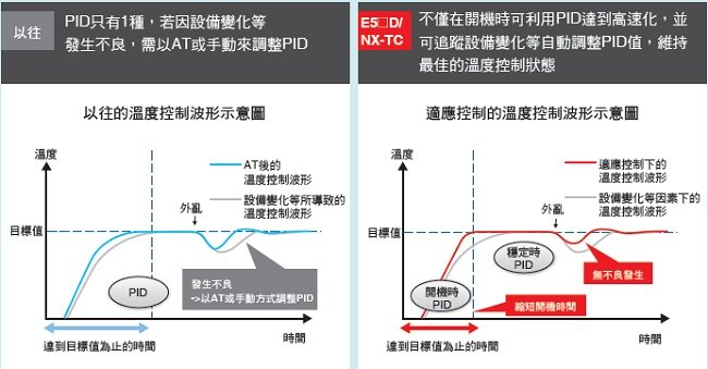
以往的溫度控制器不僅在啟動設定或變動調整上相當耗時外,且若缺乏經驗或領悟力
則難以達到最佳調整,亦對品質造成不小的影響。
為此,OMRON開發了配置「適應控制技術」的溫度控制器,該技術可像熟練者般地
掌握品質變化的狀態,執行自動調整,確保溫度控制始終處在最佳狀態。
避免繁瑣的啟動設定與調整作業,提高作業現場效率。

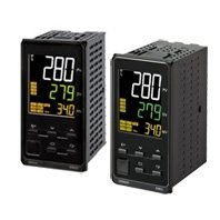
E5CD / E5CD-B
產品特色
48 x 48 mm 偵測狀態變動最佳化控制性能。 輕鬆兼顧生產力和品質要求。
藉由AI,自動實現如同熟練人員的調整。 揭開生產現場革新序幕。
無需手動作業,自動實現最佳溫度控制,輕鬆兼顧生產效率及品質。
生產線上溫度變動的主要因素
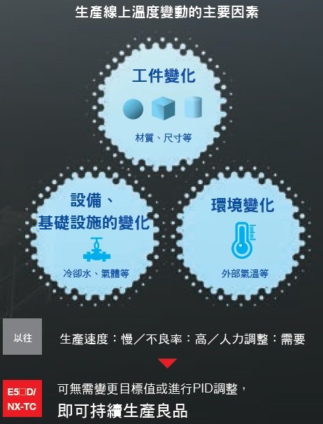
答案為業界首創*的「適應控制技術」
利用本產品所配置的「適應控制」,便可在啟動時與穩定時分別自動算出最佳的PID值。
此外,還可監視設備的溫度控制狀態,並針對工件變化與設備變化等自動調節PID值,以達到最佳的溫度控制。
*針對FA用途之通用型溫度控制器,2017年3月時的本公司調查結果。
[創造包裝機進化的新價值] 讓包裝機正確掌握封口溫度,並在自動控制與高速化的條件下維持同樣的品質。
生產現場的課題
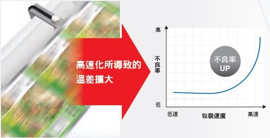
・想要透過包裝的高速化來應對新興國家的人口增加而產生的食品需求
・想要讓使用多種包材的多樣性生產達成高速化
・一旦進行高速化後,由於封口面與控制溫度之間的溫差擴大,因此導致不良率上升…
由E5[]D/NX-TC來解決
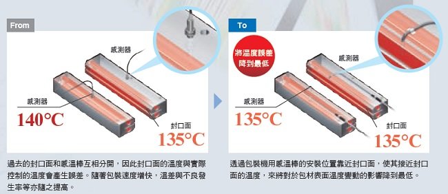
透過精確溫度測量及抑制波動技術,即能對封口面的溫度進行穩定地自動控制。
即使讓包裝工程高速化,也可藉由將封口溫度與控制溫度之間的誤差控制到最小以及穩定地自動控制,維持產品品質且實現高速化的生產。還能夠幫助包材的薄型化並且支援生產履歷。
即使是需要變更設定的多樣性生產, 也能透過自動控制來降低工時
過去因應包材的變更所做的設定變更相當耗時,因此產能無法提升。
即使是多樣性生產,亦可透過與封口溫度誤差較小的自動控制,來迅速因應生產現場的需求。
實現全新價值的控制性能
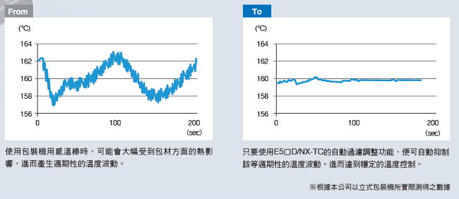
透過包裝機用感溫棒*+包裝機專用的演算法 〈自動過濾調整功能〉,將溫度誤差降到最低
*另售
量測封口面溫度的「包裝機用感溫棒」
不受包裝機速度、包材變化等溫度變動要因的影響,正確量測加熱棒表面的溫度。
表面溫度量測時能夠抑制波動的「自動過濾調整功能」
透過包裝機用感溫棒以及自動過濾調整功能的使用,得以封口溫度進行控制, 並且同時在不倚賴人力調整之下,僅由溫度控制器來抑制溫度波動。
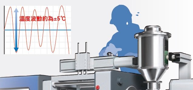
[協助成型機進化的新價值] 讓成型機進化成能夠以自動的方式穩定控制高速化所導致的溫度變化,進而使生產力達到最高。
生產現場的課題
・隨著新興國家的經濟發展、生產據點的海外移管,基礎設施相關需求不斷擴大,因此希望能夠提高生產力
・若要進行高速化,需對材料或冷卻水等引起的溫度波動進行現場調整…
・在維持品質之下進行高速生產是一個課題…
由E5[]D/NX-TC來解決
無需現場調整,即可抑制速 度變更或設備狀態變化, 所引起的溫動波動。
可檢測押出成型機在高速運轉下材料發熱處的溫度波動,以及冷卻水變動所導致的溫度波動等,進而以自動的方式穩定控制。 還可大幅降低設定工時。
另可幫助設備節能
透過穩定控制,無效的加熱用能量相較於過去,最高可減少40%的能源使用。
※根據本公司使用水冷式雙軸押出成型機所實際測得的數據
實現全新價值的控制性能
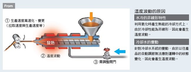
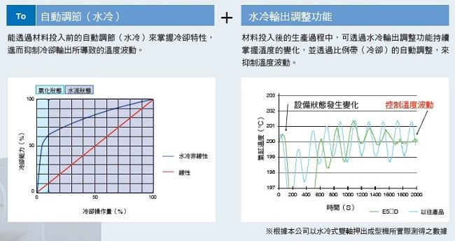
透過成型機專用的演算法〈水冷輸出調整功能〉, 將溫度波動降到最低
水冷式的押出機在進行高速化時會由於各種原因而導致溫度波動,為了品質穩定,需在現場反覆調整水閥門。
若使用E5[]D/NX-TC,則能夠以水冷輸出調整功能來將溫度波動降到最低,進而在品質不變的狀態下提高生產力。
可同時抑制溫度波動的要因,並維持穩定性能的「水冷輸出調整功能」
利用Push-In Plus端子台,即可輕鬆配線
E5[]D-B/NX-TC
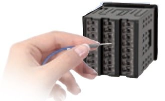
無需使用工具,僅需插入端子台即可。
降低配線作業的負擔及所需工時,新增Push-In Plus端子台系列。
大幅縮減配線所需工時
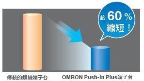
註. 上圖所示為OMRON針對Push-In Plus端子台、螺絲端子台實測後之數據。
容易插入
使用OMRON的Push-In Plus端子台就像插入耳機孔一樣簡單。減輕作業負擔,提升配線品質。

Value Design for Panel是OMRON針對控制盤產品規格的通用思維,搭配對應產品使用,為顧客的控制盤帶來嶄新的價值。
Model Number Legend
Models with Screw Terminal Blocks

Heating and Cooling Control
Using Heating and Cooling Control
(1) Control Output Assignment
An auxiliary output is used as the cooling control output.
(2) Control
If PID control is used, you can set PID control separately for heating and cooling.
This allows you to handle control systems with different heating and cooling response characteristics.
List of Models
| Model |
|---|
| E5CD-RX2A6M-000 |
| E5CD-RX2D6M-000 |
| E5CD-RX2A6M-001 |
| E5CD-RX2D6M-001 |
| E5CD-RX2A6M-002 |
| E5CD-RX2D6M-002 |
| E5CD-QX2A6M-000 |
| E5CD-QX2D6M-000 |
| E5CD-QX2A6M-001 |
| E5CD-QX2D6M-001 |
| E5CD-QX2A6M-002 |
| E5CD-QX2D6M-002 |
| E5CD-CX2A6M-000 |
| E5CD-CX2D6M-000 |
| E5CD-CX2A6M-004 |
| E5CD-CX2D6M-004 |
| E5CD-CX2A6M-006 |
| E5CD-CX2D6M-006 |
Model Number Legend
Models with Push-In Plus Terminal Blocks

Heating and Cooling Control
Using Heating and Cooling Control
(1) Control Output Assignment
An auxiliary output is used as the cooling control output.
(2) Control
If PID control is used, you can set PID control separately for heating and cooling.
This allows you to handle control systems with different heating and cooling response characteristics.
List of Models
| Model |
|---|
| E5CD-RX2ABM-000 |
| E5CD-RX2DBM-000 |
| E5CD-RX2ABM-001 |
| E5CD-RX2DBM-001 |
| E5CD-RX2ABM-002 |
| E5CD-RX2DBM-002 |
| E5CD-QX2ABM-000 |
| E5CD-QX2DBM-000 |
| E5CD-QX2ABM-001 |
| E5CD-QX2DBM-001 |
| E5CD-QX2ABM-002 |
| E5CD-QX2DBM-002 |
| E5CD-CX2ABM-000 |
| E5CD-CX2DBM-000 |
| E5CD-CX2ABM-004 |
| E5CD-CX2DBM-004 |
| E5CD-CX2ABM-006 |
| E5CD-CX2DBM-006 |
Optional Products (Order Separately)
USB-Serial Conversion Cable
| Model |
|---|
| E58-CIFQ2 |
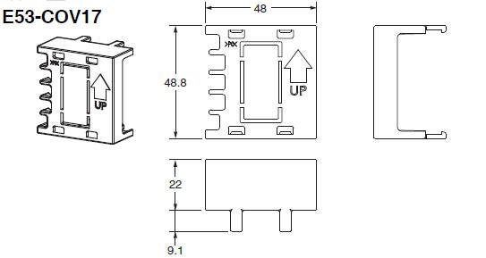
Terminal Covers
(Cannot be used on a Push-In Plus terminal block type)
| Model |
|---|
| E53-COV17 |
| E53-COV23 (3pcs) * |
Note:The E53-COV10 cannot be used. Refer to Data Sheet for the mounted dimensions.
*E53-COV23 are provided with the Digital Temperature Controller.
Waterproof Packing
| Model |
|---|
| Y92S-P8 |
Note:This Waterproof Packing is provided with the Digital Temperature Controller.
Current Transformers (CTs)
| Hole diameter | Model |
|---|---|
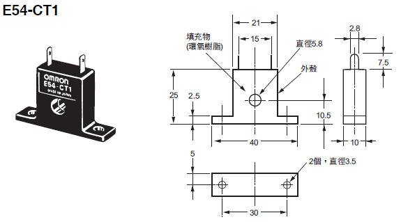
| 5.8 mm | E54-CT1 |
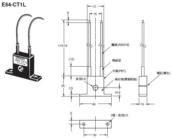
| 5.8 mm | E54-CT1L* |
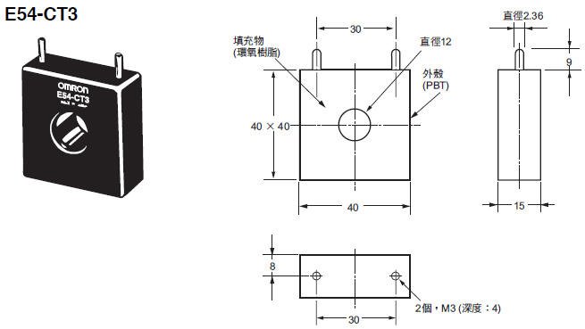
| 12.0 mm | E54-CT3 |
| 12.0 mm | E54-CT3L* |
*Lead wires are included with these CTs. If UL certification is required, use these CTs.
Adapter
| Model |
|---|
| Y92F-45 |
Note:Use this Adapter when the panel has already been prepared for an E5B[] Controller.
Waterproof Cover
| Model |
|---|
| Y92A-48N |
Mounting Adapter
| Model |
|---|
| Y92F-49 |
Note:This Mounting Adapter is provided with the Digital Temperature Controller.
DIN Track Mounting Adapter
(Cannot be used on a Push-In Plus terminal block type)
| Model |
|---|
| Y92F-52 |
Front Covers
| Type | Model |
|---|---|
| Hard Front Cover | Y92A-48H |
| Soft Front Cover | Y92A-48D |
Draw-out Jig
(Cannot be used on a Push-In Plus terminal block type)
| Model |
|---|
| Y92F-58 |
CX-Thermo Support Software
| Model |
|---|
| EST2-2C-MV4 |
Note:CX-Thermo version 4.66 or higher is required for the E5CD.
CX-Thermo version 4.67 or higher is required for the E5CD-B.
For the system requirements for the CX-Thermo, refer to information on the EST2-2C-MV4.
Ratings
| Power supply voltage | A in model number: 100 to 240 VAC, 50/60 Hz D in model number: 24 VAC, 50/60 Hz; 24 VDC |
|
|---|---|---|
| Operating voltage range | 85% to 110% of rated supply voltage | |
| Power consumption | Models with option selection of 000:5.2 VA max. at 100 to 240 VAC, and 3.1 VA max. at 24 VAC or 1.6 W max. at 24 VDC All other models: 6.5 VA max. at 100 to 240 VAC, and 4.1 VA max. at 24 VAC or 2.3 W max. at 24 VDC |
|
| Sensor input | Temperature input Thermocouple: K, J, T, E, L, U, N, R, S, B, C/W, or PL II Platinum resistance thermometer: Pt100 or JPt100 Infrared temperature sensor (ES1B): 10 to 70°C, 60 to 120°C, 115 to 165°C, or 140 to 260°C Analog input Current input:4 to 20 mA or 0 to 20 mA Voltage input:1 to 5 V, 0 to 5 V, or 0 to 10 V |
|
| Input impedance | Current input: 150 Ω max., Voltage input: 1 MΩ min. (Use a 1:1 connection when connecting the ES2-HB-N/THB-N.) |
|
| Control method | ON/OFF control or 2-PID control (with auto-tuning) | |
| Control output |
Relay output | SPST-NO, 250 VAC, 3 A (resistive load), electrical life: 100,000 operations, minimum applicable load: 5 V, 10 mA (reference value) |
| Voltage output (for driving SSR) |
Output voltage: 12 VDC ±20% (PNP), max. load current: 21 mA, with short-circuit protection circuit | |
| Linear current output |
4 to 20 or 0 to 20 mA DC, Load: 500 Ω max., Resolution: Approx. 10,000 | |
| Auxiliary output |
Number of outputs |
2 |
| Output specifications |
SPST-NO relay outputs: 250 VAC, E5CD: 3 A (resistive load), E5CD-B: 2 A (resistive load) Electrical life: 100,000 operations, Minimum applicable load: 10 mA at 5 V (reference values) |
|
| Event input |
Number of inputs |
2 |
| External contact input specifications |
Contact input: ON: 1 kΩ max., OFF: 100 kΩ min. | |
| Non-contact input: ON: Residual voltage: 1.5 V max., OFF: Leakage current: 0.1 mA max. | ||
| Current flow: Approx. 7 mA per contact | ||
| Transfer Output |
Number of outputs |
1 (depends on model): Transfer output type |
| Output specifications |
Current output: 4 to 20 mA DC, Load: 500 Ω, Resolution: Approx. 10,000 Linear voltage output: 1 to 5 V DC, Load: 1 kΩ min., Resolution: Approx. 10,000 |
|
| Setting method | Digital setting using front panel keys | |
| Indication method | 11-segment digital display, individual indicators, and bar display Character height: PV: 14.9 mm, SV: 7.1 mm |
|
| Multi SP * | Up to eight set points (SP0 to SP7) can be saved and selected using the event inputs, key operations, or serial communications. | |
| Bank switching | None | |
| Other functions | Adaptive control, automatic filter adjustment, water-cooling output adjustment, indication data (power ON time monitor, ambient temperature monitor, and control output ON/OFF count monitors), parameter masking, operation after power ON, manual output, heating/cooling control, loop burnout alarm, SP ramp, other alarm functions, heater burnout (HB) alarm (including SSR failure (HS) alarm), 40% AT, 100% AT, MV limiter, input digital filter, robust tuning, PV input shift, run/stop, protection functions, extraction of square root, MV change rate limit, logic operations, temperature status display, simple programming, moving average of input value, and display brightness setting | |
| Ambient operating temperature | -10 to 55°C (with no condensation or icing), For 3-year warranty: -10 to 50°C with standard mounting (with no condensation or icing) | |
| Ambient operating humidity | 25% to 85% | |
| Storage temperature | -25 to 65°C (with no condensation or icing) | |
| Altitude | 2,000 m max. | |
| Recommended fuse | T2A, 250 VAC, time-lag, low-breaking capacity | |
| Installation environment | Overvoltage category II, Pollution Degree 2 (EN/IEC/UL 61010-1) | |
*There can be up to four set points if event inputs are used to select them.
Input Ranges
Thermocouple/Platinum Resistance Thermometer (Universal inputs)

Analog input
| Input type | Current | Voltage | |||
|---|---|---|---|---|---|
| Input specification | 4 to 20 mA | 0 to 20 mA | 1 to 5 V | 0 to 5 V | 0 to 10 V |
| Setting range | Usable in the following ranges by scaling: -1999 to 9999, -199.9 to 999.9, -19.99 to 99.99 or -1.999 to 9.999 |
||||
| Set value | 25 | 26 | 27 | 28 | 29 |
Alarm Types
Each alarm can be independently set to one of the following 17 alarm types. The default is 2: Upper limit. (see note.)
Auxiliary outputs are allocated for alarms. ON delays and OFF delays (0 to 999 s) can also be specified.
Note:In the default settings for models with HB or HS alarms, alarm 1 is set to a heater alarm (HA) and the Alarm Type 1 parameter is not displayed.
To use alarm 1, set the output assignment to alarm 1.
| Set value |
Alarm type | Alarm output operation | Description of function | |
|---|---|---|---|---|
| When alarm value X is positive |
When alarm value X is negative |
|||
| 0 | Alarm function OFF | Output OFF | No alarm | |
| 1 | Upper- and lower-limit *1 |  |
*2 | Set the upward deviation in the set point for the alarm upper limit (H) and the lower deviation in the set point for the alarm lower limit (L). The alarm is ON when the PV is outside this deviation range. |
| 2 (default) |
Upper-limit |  |
 |
Set the upward deviation in the set point by setting the alarm value (X). The alarm is ON when the PV is higher than the SP by the deviation or more. |
| 3 | Lower-limit |  |
 |
Set the downward deviation in the set point by setting the alarm value (X). The alarm is ON when the PV is lower than the SP by the deviation or more. |
| 4 | Upper- and lower-limit range *1 |  |
*3 | Set the upward deviation in the set point for the alarm upper limit (H) and the lower deviation in the set point for the alarm lower limit (L). The alarm is ON when the PV is inside this deviation range. |
| 5 | Upper- and lower-limit with standby sequence *1 |
 |
*4 | A standby sequence is added to the upper- and lower-limit alarm (1). *6 |
| 6 | Upper-limit with standby sequence |  |
 |
A standby sequence is added to the upper-limit alarm (2). *6 |
| 7 | Lower-limit with standby sequence |  |
 |
A standby sequence is added to the lower-limit alarm (3). *6 |
| 8 | Absolute-value upper-limit |  |
 |
The alarm will turn ON if the process value is larger than the alarm value (X) regardless of the set point. |
| 9 | Absolute-value lower-limit |  |
 |
The alarm will turn ON if the process value is smaller than the alarm value (X) regardless of the set point. |
| 10 | Absolute-value upper-limit with standby sequence |  |
 |
A standby sequence is added to the absolute-value upper-limit alarm (8). *6 |
| 11 | Absolute-value lower-limit with standby sequence |  |
 |
A standby sequence is added to the absolute-value lower-limit alarm (9). *6 |
| 12 | LBA (alarm 1 type only) | - | *7 | |
| 13 | PV change rate alarm | - | *8 | |
| 14 | SP absolute-value upper-limit alarm |  |
 |
This alarm type turns ON the alarm when the set point (SP) is higher than the alarm value (X). |
| 15 | SP absolute-value lower-limit alarm |  |
 |
This alarm type turns ON the alarm when the set point (SP) is lower than the alarm value (X). |
| 16 | MV absolute-value upper-limit alarm *9 | Standard Control |
Standard Control |
This alarm type turns ON the alarm when the manipulated variable (MV) is higher than the alarm value (X). |
| Heating/Cooling Control (Heating MV)  |
Heating/Cooling Control (Heating MV) Always ON |
|||
| 17 | MV absolute-value lower-limit alarm *9 | Standard Control |
Standard Control |
This alarm type turns ON the alarm when the manipulated variable (MV) is lower than the alarm value (X). |
| Heating/Cooling Control (Cooling MV)  |
Heating/Cooling Control (Cooling MV) Always ON |
|||
*1.With set values 1, 4 and 5, the upper and lower limit values can be set independently for each alarm type, and are
expressed as “L” and “H.”
*2.Set value: 1, Upper- and lower-limit alarm
*3.Set value: 4, Upper- and lower-limit range
*4.Set value: 5, Upper- and lower-limit with standby sequence For Upper- and Lower-Limit Alarm Described Above *2
• Case 1 and 2
Always OFF when the upper-limit and lower-limit hysteresis overlaps.
• Case 3: Always OFF
*5.Set value: 5, Upper- and lower-limit with standby sequence
Always OFF when the upper-limit and lower-limit hysteresis overlaps.
*6.Refer to the E5[]D Digital Temperature Controllers User's Manual (Cat. No. H224) for information on the operation
of the standby sequence.
*7.Refer to the E5[]D Digital Temperature Controllers User's Manual (Cat. No.H224) for information on the loop burnout
alarm (LBA).
*8.Refer to the E5[]D Digital Temperature Controllers User's Manual (Cat. No. H224) for information on the PV change
rate alarm.
*9.When heating/cooling control is performed, the MV absolute upper limit alarm functions only for the heating operation
and the MV absolute lower limit alarm functions only for the cooling operation.
Characteristics
| Indication accuracy (at the ambient temperature of 23°C) |
Thermocouple: (±0.3% of indication value or ±1°C, whichever is greater) ±1 digit max. *1 Platinum resistance thermometer: (±0.2% of indication value or ±0.8°C, whichever is greater) ±1 digit max. Analog input: ±0.2% FS ±1 digit max. CT input: ±5% FS ±1 digit max. |
|
|---|---|---|
| Transfer output accuracy | ±0.3% FS max. | |
| Influence of temperature *2 | Thermocouple input (R, S, B, C/W, PL II): (±1% of indication value or ±10°C, whichever is greater) ±1 digit max. Other thermocouple input: (±1% of indication value or ±4°C, whichever is greater) ±1 digit max. *3 Platinum resistance thermometer: (±1% of indication value or ±2°C, whichever is greater) ±1 digit max. Analog input: ±1%FS ±1 digit max. CT input: ±5% FS ±1 digit max. |
|
| Influence of voltage *2 | ||
| Influence of EMS. (at EN 61326-1) |
||
| Input sampling period | 50 ms | |
| Hysteresis | Temperature input: 0.1 to 999.9°C or °F (in units of 0.1°C or °F) Analog input: 0.01% to 99.99% FS (in units of 0.01% FS) |
|
| Proportional band (P) | Temperature input: 0.1 to 999.9°C or °F (in units of 0.1°C or °F) Analog input: 0.1% to 999.9% FS (in units of 0.1% FS) |
|
| Integral time (I) | 0 to 9999 s (in units of 1 s), 0.0 to 999.9 s (in units of 0.1 s) *4 | |
| Derivative time (D) | 0 to 9999 s (in units of 1 s), 0.0 to 999.9 s (in units of 0.1 s) *4 | |
| Proportional band (P) for cooling | Temperature input: 0.1 to 999.9°C or °F (in units of 0.1°C or °F) Analog input: 0.1% to 999.9% FS (in units of 0.1% FS) |
|
| Integral time (I) for cooling | 0 to 9999 s (in units of 1 s), 0.0 to 999.9 s (in units of 0.1 s) *4 | |
| Derivative time (D) for cooling | 0 to 9999 s (in units of 1 s), 0.0 to 999.9 s (in units of 0.1 s) *4 | |
| For adaptive control |
SP response proportional band |
Temperature input: 0.1 to 999.9°C or °F (in units of 0.1°C or °F) |
| SP response integral time |
0 to 9999 s (in units of 1 s), 0.0 to 999.9 s (in units of 0.1 s) *4 | |
| SP response derivative time |
0 to 9999 s (in units of 1 s), 0.0 to 999.9 s (in units of 0.1 s) *4 | |
| Disturbance proportional band |
Temperature input: 0.1 to 999.9°C or °F (in units of 0.1°C or °F) | |
| Disturbance integral time |
0 to 9999 s (in units of 1 s), 0.0 to 999.9 s (in units of 0.1 s)*4 | |
| Disturbance derivative time |
0 to 9999 s (in units of 1 s), 0.0 to 999.9 s (in units of 0.1 s) *4 | |
| Control period | 0.1, 0.2, 0.5, 1 to 99 s (in units of 1 s) | |
| Manual reset value | 0.0 to 100.0% (in units of 0.1%) | |
| Alarm setting range | -1999 to 9999 (decimal point position depends on input type) | |
| Influence of signal source resistance |
Thermocouple: 0.1°C/Ω max. (100 Ω max.) Platinum resistance thermometer: 0.1°C/Ω max. (10 Ω max.) |
|
| Insulation resistance | 20 MΩ min. (at 500 VDC) | |
| Dielectric strength | 3,000 VAC, 50/60 Hz for 1 min between terminals of different charge | |
| Vibration | Malfunction | 10 to 55 Hz, 20 m/s2 for 10 min each in X, Y, and Z directions |
| Resistance | 10 to 55 Hz, 20 m/s2 for 2 hrs each in X, Y, and Z directions | |
| Shock | Malfunction | 100 m/s2, 3 times each in X, Y, and Z directions |
| Resistance | 300 m/s2, 3 times each in X, Y, and Z directions | |
| Weight | Controller: Approx. 120 g, Mounting Adapter: Approx. 10 g | |
| Degree of protection | Front panel: IP66, Rear case: IP20, Terminals: IP00 | |
| Memory protection | Non-volatile memory (number of writes: 1,000,000 times) | |
| Setup Tool | E5CD: CX-Thermo version 4.66 or higher E5CD-B: CX-Thermo version 4.67 or higher |
|
| Setup Tool port | E5CD/E5CD-B top panel: An E58-CIFQ2 USB-Serial Conversion Cable is used to connect to a USB port on the computer.*5 | |
| Standards | Approved standards |
cULus: UL 61010-1/CSA C22.2 No.61010-1, Korean wireless regulations (Radio law: KC Mark) |
| Conformed standards |
EN 61010-1 (IEC 61010-1) and RCM standards | |
| EMC | EMI: EN 61326-1 *6 Radiated Interference Electromagnetic Field Strength: EN 55011 Group 1, class A Noise Terminal Voltage:EN 55011 Group 1, class A EMS:EN 61326-1 *6 ESD Immunity:EN 61000-4-2 Electromagnetic Field Immunity:EN 61000-4-3 Burst Noise Immunity:EN 61000-4-4 Conducted Disturbance Immunity:EN 61000-4-6 Surge Immunity:EN 61000-4-5 Voltage Dip/Interrupting Immunity:EN 61000-4-11 |
|
*1.The indication accuracy of K thermocouples in the −200 to 1,300°C range, T and N thermocouples at a temperature of −100°C max., and U and L thermocouples at any temperatures is ±2°C ±1 digit max. The indication accuracy of the B thermocouple at a temperature of 400°C max. is not specified. The indication accuracy of B thermocouples at a temperature of 400 to 800°C is ±3°C max. The indication accuracy of the R and S thermocouples at a temperature of 200°C max. is ±3°C ±1 digit max. The indication accuracy of C/W thermocouples is (±0.3% of PV or ±3°C, whichever is greater) ±1 digit max. The indication accuracy of PL II thermocouples is (±0.3% of PV or ±2°C, whichever is greater) ±1 digit max.
*2.Ambient temperature: −10°C to 23°C to 55°C, Voltage range: −15% to 10% of rated voltage
*3.K thermocouple at −100°C max.: ±10°C max.
*4.The unit is determined by the setting of the Integral/Derivative Time Unit parameter.
*5.External communications (RS-485) and USB-serial conversion cable communications can be used at the same time.
*6.Industrial electromagnetic environment (EN/IEC 61326-1 Table 2)
USB-Serial Conversion Cable
| Applicable OS | Windows XP/Vista/7/8/8.1/10 *1 |
|---|---|
| Applicable software | CX-Thermo version 4.66 or higher (E5CD-B: version 4.67 or higher) |
| Applicable models | E5[]C-T Series, E5[]C Series, E5CB Series, and E5[]D Series |
| USB interface standard | Conforms to USB Specification 2.0. |
| DTE speed | 38,400 bps |
| Connector specifications | Computer: USB (type A plug) Digital Temperature Controller: Special serial connector |
| Power supply | Bus power (Supplied from USB host controller.)*2 |
| Power supply voltage | 5 VDC |
| Current consumption | 450 mA max. |
| Output voltage | 4.7±0.2 VDC (Supplied from USB-Serial Conversion Cable to the Digital Temperature Controller.) |
| Output current | 250 mA max. (Supplied from USB-Serial Conversion Cable to the Digital Temperature Controller.) |
| Ambient operating temperature | 0 to 55°C (with no condensation or icing) |
| Ambient operating humidity | 10% to 80% |
| Storage temperature | -20 to 60°C (with no condensation or icing) |
| Storage humidity | 10% to 80% |
| Altitude | 2,000 m max. |
| Weight | Approx. 120 g |
Windows is a registered trademark of Microsoft Corporation in the United States and or other countries.
*1.CX-Thermo version 4.65 or higher runs on Windows 10.
*2.Use a high-power port for the USB port.
Note:A driver must be installed on the computer. Refer to the Instruction Manual included with the Cable for the installation procedure.
Communications Specifications
| Transmission line connection method | RS-485: Multidrop |
|---|---|
| Communications | RS-485 (two-wire, half duplex) |
| Synchronization method | Start-stop synchronization |
| Protocol | CompoWay/F, or Modbus |
| Baud rate * | 9,600, 19,200, 38,400, 57,600, or 115,200 bps |
| Transmission code | ASCII |
| Data bit length * | 7 or 8 bits |
| Stop bit length * | 1 or 2 bits |
| Error detection | Vertical parity (none, even, odd) Block check character (BCC) with CompoWay/F or CRC-16 Modbus |
| Flow control | None |
| Interface | RS-485 |
| Retry function | None |
| Communications buffer | 217 bytes |
| Communications response wait time | 0 to 99 ms Default: 20 ms |
*The baud rate, data bit length, stop bit length, and vertical parity can be individually set using the Communications Setting Level.
Communications Functions
| Programless communications |
You can use the memory in the PLC to read and write E5CD/E5CD-B parameters, start and stop operation, etc. The E5CD/E5CD-B automatically performs communications with PLCs. No communications programming is required. Number of connected Digital Temperature Controllers: 32 max. (Up to 16 for the FX3) Applicable PLCs OMRON PLCs CS Series, CJ Series, CP Series, NJ Series, or NX1P Mitsubishi Electric PLCs MELSEC Q Series, L Series, FX3 Series, or iQ-R Series KEYENCE PLCs KEYENCE KV Series |
|---|---|
| Copying * | When Digital Temperature Controllers are connected, the parameters can be copied from the Digital Temperature Controller that is set as the master to the Digital Temperature Controllers that are set as slaves. |
MELSEC is a registered trademark of Mitsubishi Electric Corporation.
KEYENCE is a registered trademark of Keyence Corporation.
*Programless communications supports the copying function.
Current Transformer (Order Separately) Ratings
| E54-CT1 E54-CT3 |
E54-CT1L E54-CT3L |
|
|---|---|---|
| Dielectric strength | 1,000 VAC for 1 min | 1,500 VAC for 1 min |
| Vibration resistance | 50 Hz, 98 m/s2 | |
| Weight | E54-CT1: Approx. 11.5 g E54-CT3: Approx. 50 g |
E54-CT1L: Approx. 14 g E54-CT3L: Approx. 57 g |
| Accessories | E54-CT3 Only Armatures (2) Plugs (2) |
None |
Heater Burnout Alarms and SSR Failure Alarms
| CT input (for heater current detection) | Models with detection for single-phase heaters: One input |
|---|---|
| Maximum heater current | 50 A AC |
| Input current indication accuracy | ±5% FS ±1 digit max. |
| Heater burnout alarm setting range *1 | 0.1 to 49.9 A (in units of 0.1 A) Minimum detection ON time: 100 ms *3 |
| SSR failure alarm setting range *2 | 0.1 to 49.9 A (in units of 0.1 A) Minimum detection OFF time: 100 ms *4 |
*1.For heater burnout alarms, the heater current will be measured when the control output is ON, and the output will turn ON if the heater current is lower than the set value (i.e., heater burnout detection current value).
*2.For SSR failure alarms, the heater current will be measured when the control output is OFF, and the output will turn ON if the heater current is higher than the set value (i.e., SSR failure detection current value).
*3.The value is 30 ms for a control period of 0.1 s or 0.2 s.
*4.The value is 38 ms for a control period of 0.1 s or 0.2 s.
Electrical Life Expectancy Curve for Control Output Relay (Reference Values)
(單位:mm)
Controllers
E5CD
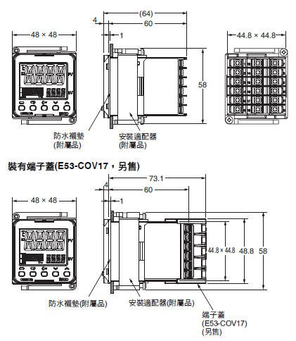
E5CD-B
The Setup Tool port is on the top of the Digital Temperature Controller.
It is used to connect the Digital Temperature Controller to the computer to use the Setup Tool.
The E58-CIFQ2 USB-Serial Conversion Cable is required to make the connection.
Refer to the instructions that are provided with the USB-Serial Conversion Cable for the connection procedure.
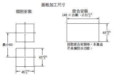
• Recommended panel thickness is 1 to 5 mm.
• Group mounting is not possible in the vertical direction. (Main-tain the specified mounting space between Controllers.)
• To mount the Controller so that it is waterproof, insert the water-proof packing onto the Controller.
• When two or more Controllers are mounted, make sure that the surrounding temperature does not exceed the allowable operat-ing temperature specified in the specifications.
• Use a control panel thickness of 1 to 3 mm if the Y92A-48N and a USB-Serial Conversion Cable are used together.
• Use a control panel thickness of 1 to 3 mm if the Y92S-P8 and a USB-Serial Conversion Cable are used together.
Note: Do not leave the USB-Serial Conversion Cable connected when you use the Digital Temperature Controller.
Accessories (Order Separately)
USB-Serial Conversion Cable
E58-CIFQ2
Terminal Covers (Cannot be used on a Push-In Plus terminal block type)
E53-COV17
Terminal Covers (Cannot be used on a Push-In Plus terminal block type)
E53-COV23 (Three Covers provided.)
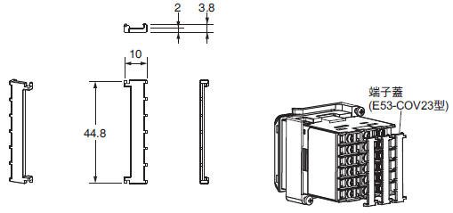
The Terminal Covers are provided with the Digital Temperature Controller.
Order the Terminal Cover separately if it becomes lost or damaged.
Waterproof Packing
Y92S-P8 (for DIN 48 × 48)
The Waterproof Packing is provided with the Digital Temperature Controller. Order the Waterproof Packing separately if it becomes lost or damaged. The Waterproof Packing can be used to achieve an IP66 degree of protection. (Deterioration, shrinking, or hardening of the waterproof packing may occur depending on the operating environment. Therefore, periodic replacement is recommended to ensure the level of waterproofing specified in IP66. The time for periodic replacement depends on the operating environment. Be sure to confirm this point at your site. Consider three years as rough standard.)
Current Transformers
E54-CT1
E54-CT1L
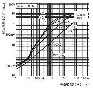
Thru-current (Io) vs. Output Voltage (Eo)
(Reference Values)
E54-CT1 or E54-CT1L
Maximum continuous heater current: 50 A (50/60 Hz)
Number of windings: 400±2
Winding resistance: 18±2 Ω
E54-CT3
E54-CT3 Accessories
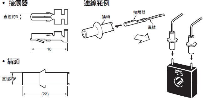
E54-CT3L
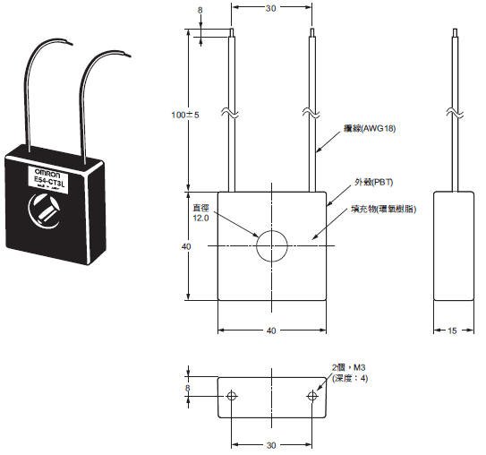
Thru-current (Io) vs. Output Voltage (Eo)
(Reference Values)
E54-CT3 or E54-CT3L
Maximum continuous heater current: 120 A (50/60 Hz)
(Maximum continuous heater current for an OMRON Digital Temperature Controller is 50 A.)
Number of windings: 400±2
Winding resistance: 8±0.8 ΩThru
Adapter
Y92F-45
Note:
1. Use this Adapter when the Front Panel has already been prepared for the E5B[].
2. Only black is available.
3. You cannot use the E58-CIFQ2 USB-Serial Conversion Cable if you use the Y92F-45 Adapter. To use the USB-Serial
Conversion Cable to make the settings, do so before you mount the Digital Temperature Controller in the panel.
4. You cannot use it together with the Y92F-49 Adapter that is enclosed with the Controller.
Mounting Example
DIN Track Mounting Adapter (Cannot be used on a Push-In Plus terminal block type)
Y92F-52
Note: This Adapter cannot be used together with the Terminal Cover.
Remove the Terminal Cover to use the Adapter.
This Adapter is used to mount the E5CD to a DIN Track.
If you use the Adapter, there is no need for a plate to mount in the panel or to drill mounting holes in the panel.
Mounting Example
Waterproof Cover
Y92A-48N
Mounting Adapter
Y92F-49
The Mounting Adapter is provided with the Digital Temperature Controller.
Order this Adapter separately if it becomes lost or damaged.
Front Cover
Y92A-48D
Note: This Front Cover cannot be used if the Waterproof Packing is installed.
This Front Cover is soft type. It is able to operate the controller with using this cover.
Front Cover
Y92A-48H
This Front Cover is hard type. Please use it for the mis-operation prevention etc.
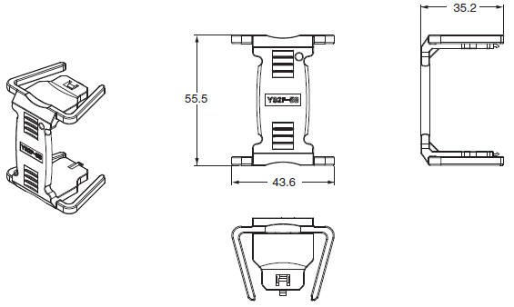
Draw-out Jig (Cannot be used on a Push-In Plus terminal block type)
Y92F-58
Use this Draw-out Jig to remove the interior body of the Digital Temperature Controller from the case to perform maintenance without removing the terminal wiring.
中文
| 型錄名稱 | 型錄編號 [容量] |
更新日期 | |
|---|---|---|---|
| H226-E1-TW5 [20833KB] |
2019年1月29日
20190129
|
E5[]D/NX-TC 型錄 |
English
Global Edition
| Catalog Name | Catalog Number [size] |
Last Update | |
|---|---|---|---|
| H223-E1-05 [14385KB] |
Nov 08, 2021
20211108
|
E5[]D Data Sheet | |
| H222-E1-04 [2814KB] |
Oct 01, 2019
20191001
|
E5[]D/NX-TC Catalog | |
| Y235-E1-01 [5944KB] |
Jul 19, 2022
20220719
|
Value Design for Panel Catalog |
如有需要請洽各所營業人員
誠睿台南所 TEL:06-2493086
誠睿台中所 TEL:04-23380790
誠睿新竹所 TEL:03-6685558
客服信箱 service@hitifa.com.tw
誠睿台南所 TEL:06-2493086
誠睿台中所 TEL:04-23380790
誠睿新竹所 TEL:03-6685558
客服信箱 service@hitifa.com.tw
如有需要請洽各所營業人員
誠睿台南所 TEL:06-2493086
誠睿台中所 TEL:04-23380790
誠睿新竹所 TEL:03-6685558
客服信箱 service@hitifa.com.tw
誠睿台南所 TEL:06-2493086
誠睿台中所 TEL:04-23380790
誠睿新竹所 TEL:03-6685558
客服信箱 service@hitifa.com.tw