The H7CC series improves overall user experience through better visual feedback and operation, user interface and predictive remaining lifetime of counter.

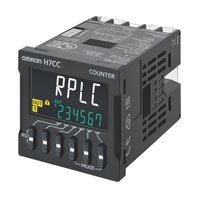
H7CC-A
產品特色
New and improved design for easier use, programming, maintenance and user feedback. The improved user interface is intuitive and offers better overall visibility. Replacement time notification function notifies the user of potential preventive maintenance
New and improved design for easier use, setting and maintenace
The improved user interface is intuitive and offers better overall visibility

Intuitive LED user-interface guide

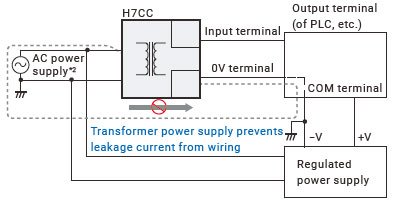
Optimized wiring design
Power supply and input have been isolated, eliminating special considerations for grounding or leakage current.
Replacement time notification function notifies the user of potential preventive maintenance
[From] Have you ever looked at a counter to find that it has stopping functioning properly?
When a counter’s service life expires, there are multiple ways it can potentially fail. For example, it may stop suddenly or become incapable of performing certain control functions.
Preventative maintenance to avoid such mechanical failures or identifying the cause when such a failure occurs, may require a significant effort and time.
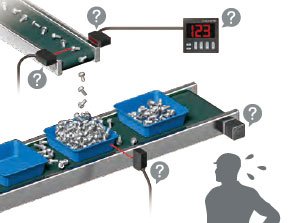
A single error may have several contributing factors
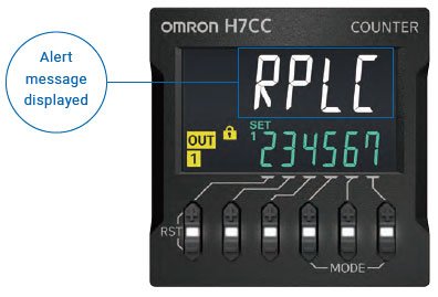
[To] Prevents unexpected downtime by communicating device replacement timing
When an H7CC Series counter reaches its replacement time, it will visually notify the user via its display by flashing the count value and “RPLC” alternately in one second intervals.
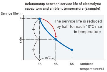
Tool for easily calculating counter replacement time
The rate at which an electrolytic capacitor deteriorates varies according to its use environment. Omron offers a tool that allows you to easily calculate your H7CC counter’s replacement time, according to the conditions your using it in.
Control devices, including counters, have a limited service life
Each counter has its limited service life.
The standard service life of a relay output contact is 100,000 operations. Factoring in the deterioration of the built-in electrolytic capacitors, Omron recommends that a counter be replaced approximately every 7 to 10 years depending on environment. A counter that is used beyond its service life may fail, potentially emitting smoke or odor.
*1. Compared with the previous products
*2. The AC power supply ground is on the commercial power supply side.
Model Number Legend (Not all possible combinations of functions are available.)
List of Models
| Classification | Configuration | External connections |
Settings | Display digits |
Outputs | Power supply voltage |
Model |
|---|---|---|---|---|---|---|---|
| Preset counter | • 1-stage preset counter • Total and preset counter |
8-pin socket | 1-stage | 6 digits | Contact output (SPST) |
100 to 240 VAC |
H7CC-A8 |
| 24 VAC/ 12 to 48 VDC |
H7CC-A8D | ||||||
| 11-pin socket | Contact output (SPDT) |
100 to 240 VAC |
H7CC-A11 | ||||
| Transistor output (SPST) |
H7CC-A11S | ||||||
| Contact output (SPDT) |
24 VAC/ 12 to 48 VDC |
H7CC-A11D | |||||
| Transistor output (SPST) |
H7CC-A11SD | ||||||
| Screw terminals |
Contact output (SPDT) |
100 to 240 VAC |
H7CC-A | ||||
| Transistor output (SPST) |
H7CC-AS | ||||||
| Contact output (SPDT) |
24 VAC/ 12 to 48 VDC |
H7CC-AD | |||||
| Transistor output (SPST) |
H7CC-ASD | ||||||
| Preset counter/ Tachometer |
• 1-stage preset counter • 2-stage preset counter • Total and preset counter • Batch counter • Dual counter • Twin counter • Tachometer |
2-stage | Contact output (SPST+SPDT) |
100 to 240 VAC |
H7CC-AW | ||
| Transistor output (DSPT) |
H7CC-AWS | ||||||
| Contact output (SPST+SPDT) |
24 VAC/ 12 to 48 VDC |
H7CC-AWD | |||||
| Transistor output (DSPT) |
H7CC-AWSD | ||||||
| Contact output (SPDT) + Transistor output (SPST) |
100 to 240 VAC |
H7CC-AU | |||||
| 24 VAC/ 12 to 48 VDC |
H7CC-AUD |
Accessories (Order Separately)
Soft Cover
| Model | Remarks |
|---|---|
| Y92A-48F1 | --- |
Hard Cover
| Model | Remarks |
|---|---|
| Y92A-48 | --- |
Flush Mounting Adapter
| Model | Remarks |
|---|---|
| Y92F-30 | Included with models with screw terminals. |
| Y92F-45 | Use this Adapter to install the Counter/Tachometer in a cutout previously made for a DIN 72 × 72 mm device (panel cutout: 68 × 68 mm). |
Waterproof Packing
| Model | Remarks |
|---|---|
| Y92S-P6 | Included with models with screw terminals. |
Connection Sockets
| Model | Classification | Connectable Counter/ Tachometers |
Remarks |
|---|---|---|---|
| P2CF-08 | Front-connecting Socket | H7CC-[]8 | --- |
| P2CF-08-E | Front-connecting Socket (Finger-safe Type) |
Round crimp terminals cannot be used on Finger-safe Sockets. Use forked crimp terminals. |
|
| P3G-08 | Back-connecting Sockets | A Y92A-48G Terminal Cover can be used with the Socket to create a finger-safe construction. |
|
| P2CF-11 | Front-connecting Socket | H7CC-[]11 | --- |
| P2CF-11-E | Front-connecting Socket (Finger-safe Type) |
Round crimp terminals cannot be used on Finger-safe Sockets. Use forked crimp terminals. |
|
| P3GA-11 | Back-connecting Sockets | A Y92A-48G Terminal Cover can be used with the Socket to create a finger-safe construction. |
Terminal Covers for P3GA-11 Back-connecting Socket
| Model | Remarks |
|---|---|
| Y92A-48G | --- |
Ratings
| Item | H7CC-A8/-A11[] | H7CC-A[] | H7CC-AW[]/AU[] | |
|---|---|---|---|---|
| Classification | Preset counter | Preset counter/ tachometer | ||
| Configuration | 1-stage preset counter, 1-stage preset counter with total counter (selectable) *1 | 1-stage/2-stage preset counter, total and preset counter *1, batch counter, dual counter, twin counter, and tachometer (selectable) |
||
| Ratings | Power supply voltage *2 |
• 100 to 240 VAC, 50/60 Hz • 24 VAC, 50/60 Hz or 12 to 48 VDC |
||
| Operating voltage fluctuation range |
85% to 110% of rated supply voltage (12 to 48 VDC: 90% to 110%) | |||
| Power consumption |
Approx. 6.8 VA at 100 to 240 VAC, Approx. 5.5 VA/3.3 W at 24 VAC/12 to 48 VDC, |
|||
| Mounting method | Flush mounting or surface mounting | Flush mounting | ||
| External connections | 8-pin/ 11-pin socket | Screw terminals | ||
| Degree of protection | IEC IP66 for panel surface only and only when Y92S-P6 Waterproof Packing is used. | |||
| Input signals | CP1, CP2, reset, and total reset *4 | CP1, CP2, reset 1, and reset 2 | ||
| Counter | Maximum counting speed |
30 Hz (minimum pulse width: 16.7 ms) or 10 kHz (minimum pulse width: 0.05 ms) (selectable) (ON/OFF ratio 1:1) *Common setting for CP1 and CP2 |
||
| Input mode |
Increment (UP), decrement (DOWN), increment/decrement (UP/DOWN A (command input), UP/DOWN B (individual inputs), or UP/DOWN C (quadrature inputs)), UP/DOWN D (command input), UP/DOWN E (individual inputs), UP/DOWN E (quadrature inputs) | |||
| Output mode |
N, F, C, R, K-1, P, Q, A, K-2, D, and L. | N, F, C, R, K-1, P, Q, A, K-2, D, L, and H. | ||
| One-shot out put time |
0.01 to 99.99 s | |||
| Reset system |
External (minimum reset signal width: 1 ms or 20 ms, selectable), manual, and automatic reset (internal according to C, R, P, and Q mode operation) | |||
| Tachometer | Refer to the tachometer function ratings. | |||
| Prescaling function | Yes (0.001 to 99.999) | |||
| Decimal point adjustment | Yes (right most 3 digits) | |||
| Sensor waiting time | 290 ms max. (Control output is turned OFF and no input is accepted during sensor waiting time.) | |||
| Input method | No-voltage (NPN) input/voltage (PNP) input (switchable) No-voltage inputs: ON impedance: 1 kΩ max. (Leakage current: 12 mA at 0 Ω) ON residual voltage: 3 V max. OFF impedance: 100 kΩ min. Voltage input: High (logic) level: 4.5 to 30 VDC Low (logic) level: 0 to 2 VDC (Input resistance: approx. 4.7 kΩ) |
|||
| External power supply | 12 VDC (±10%), 100 mA (except for H7CC-A8[] models) Refer to Precautions for Correct Use on Catalog for details. | |||
| Control output | • Contact output: 3 A at 250 VAC/30 VDC, resistive load (cosφ=1), Minimum applied load: 10 mA at 5 VDC (failure level: P, reference value) • Transistor output: NPN open collector, 100 mA at 30 VDC, Residual voltage: 1.5 VDC max. (approx. 1 V), Leakage current: 0.1 mA max. |
|||
| Display *3 | 7-segment, negative transmissive LCD Character height Count value: 10 mm (white) Set value: 6 mm (green) |
|||
| Digits | 6 digits -99999 to 999999 (-5 digits to +6 digits) |
6 digits -99999 to 999999 (-5 digits to +6 digits), tachometer: 0 to 999999 |
||
| Memory backup | Non-volatile memory (overwrites: 100,000 times min.) that can store data for 10 years min. | |||
| Operating temperature range | -10 to 55°C (-10 to 50°C if Counter/Tachometers are mounted side by side) (with no icing or condensation) | |||
| Storage temperature range | -25 to 70°C (with no icing or condensation) | |||
| Operating humidity range | 25% to 85% | |||
| Case color | Black (N1.5) | |||
| Attachments | --- | Flush mounting adapter, waterproof packing, terminal cover | ||
*1. 1-stage preset counter and total counter functionality.
*2. Do not use the output from an inverter as the power supply.The ripple must be 20% maximum for DC power.
*3. The display is lit only when the power is ON. Nothing is displayed when power is OFF.
*4. Only reset input is performed in the H7CC-A8[], and the total count is also reset simultaneously.
Tachometer Function Ratings
| Item | H7CC-A8[] H7CC-A11[] H7CC-A[] |
H7CC-AW[]/AU[] | |||
|---|---|---|---|---|---|
| Input mode | No tachometer functionality |
Selectable from 1 inputs, independent measurements for 2 inputs, differential input for 2 inputs, absolute ratio for 2 inputs, and error ratio for 2 inputs. |
|||
| Pulse measurement method |
Periodic measurement | Pulse width measurement | |||
| Maximum counting speed |
30 Hz (minimum pulse width: 16.7 ms) |
1-input mode: 10 kHz (minimum pulse width: 0.05 ms) Other modes: 5 kHz (minimum pulse width: 0.1 ms) |
30 Hz (minimum pulse width: 16.7 ms) |
1-input mode: 10 kHz (minimum pulse width: 0.05 ms) Other modes: 5 kHz (minimum pulse width: 0.1 ms) |
|
| Minimum input signal width |
--- | --- | 30 ms * | 1-input mode: 0.2 ms Other modes: 0.4 ms* |
|
| Measuring ranges | 0.001 to 30.00 Hz | 1-input mode: 0.001 to 10 kHz, Other modes: 0.01 to 5 kHz |
0.030 to 999999 s | 1-input mode: 0.0002 to 999999 s Other modes: 0.0004 to 999999 s |
|
| Sampling period | 200 ms min. | 200 ms min. or continuous selectable (minimum interval of 10 ms) |
Continuous (minimum interval of 10 ms) | ||
| Measuring accuracy | ±0.1% FS ±1 digit max. (at 23 ±5°C) | ||||
| Output mode | Input mode: Not 2-input independent measurement: HI-LO, AREA, HI-HI, LO-LO 2-input independent measurement: HI-HI, LO-LO |
||||
| Auto-zero time | 0.1 to 999.9s | ||||
| Startup time | 0.0 to 99.9s | ||||
| Averaging | Simple averaging/moving averaging selectable, Processing: OFF, 2, 4, 8, or 16 times | ||||
| Hold input | Minimum input signal width: 20 ms | ||||
* An input OFF time of at least 20 ms is required.
Characteristics
| Insulation resistance | 100 MΩ min. (at 500 VDC) between current-carrying terminals and exposed non-current-carrying metal parts, and between non-continuous contacts | |
|---|---|---|
| Dielectric strength | 2,000 VAC, 50/60 Hz for 1 min between current-carrying metal parts and non-current-carrying metal parts 2,000 VAC, 50/60 Hz for 1 min between power supply and input circuit for all models except H7CC-[]D[] (1,500 VAC for 24 VAC/12 to 48 VDC) 1,500 VAC (for H7CC-[]SD[]), 50/60 Hz for 1 min between control output, power supply, and input circuit (2,000 VACfor models other than H7CC-[]SD[]) 1,000 VAC, 50/60 Hz for 1 min between non-continuous contacts |
|
| Impulse withstand voltage | 6.0 kV between power terminals (1.0 kV for models with 24 VAC/12 to 48 VDC) 6.0 kV between current-carrying terminals and exposed non-current-carrying metal parts (1.5 kV for models with 24 VAC/12 to 48 VDC) |
|
| Static immunity | Malfunction: 8 kV Destruction: 15 kV |
|
| Vibration resistance |
Destruction | 10 to 55 Hz with 0.75-mm single amplitude each in three directions for 2 h each |
| Malfunction | 10 to 55 Hz with 0.35-mm single amplitude each in three directions for 10 min each | |
| Shock resistance |
Destruction | 300 m/s2 each in three directions |
| Malfunction | 100 m/s2 each in three directions | |
| Life expectancy | Mechanical: 10,000,000 operations min. Electrical: 100,000 operations min. (3 A at 250 VAC, resistive load, ambient temperature condition: 23°C) * |
|
| Weight | Approx. 120 g (Counter only) | |
* Refer to the Life-test Curve.
Life-test Curve (Reference Values)
A current of 0.15 A max. can be switched at 125 VDC (cosφ=1) and current of 0.1 A max. can be switched if L/R=7 ms. In both cases, a life of 100,000 operations can be expected.
Applicable Standards
| Approved safety standards |
cULus (or cURus): UL508/CSA C22.2 No. 14 *1 EN 61010-1 (IEC 61010-1): Pollution degree 2/overvoltage category II EAC RCM B300 PILOT DUTY 1/4 HP 120 VAC, 1/3 HP, 240 VAC, 3 A, 250 VAC/30 VDC resistive load VDE0106/part100 |
|---|---|
| EMC | (EMI) EN61326-1 *2 Emission Enclosure: EN 55011 Group 1 class A Emission AC mains: EN 55011 Group 1 class A (EMS) EN61326-1 *2 Immunity ESD: EN 61000-4-2: 4 kV contact discharge; 8 kV air discharge Immunity RF-interference: EN 61000-4-3: 10 V/m (Amplitude-modulated, 80 MHz to 1 GHz) 3 V/m (Amplitude-modulated, 1.4 G to 2 GHz) 1 V/m (Amplitude-modulated, 2 G to 2.7 GHz) 10 V/m (Pulse-modulated, 900 MHz ±5 MHz) Immunity Conducted Disturbance: EN 61000-4-6: 10 V (0.15 to 80 MHz) Immunity Burst: EN 61000-4-4: 2 kV power-line; 1 kV I/O signal-line Immunity Surge: EN 61000-4-5: 1 kV line to lines (power and output lines); 2 kV line to ground (power and output lines) Immunity Voltage Dip/Interruption: EN 61000-4-11: Voltage Dip 1 cycle, 100% (rated voltage) 10/12 cycle 60% (rated voltage) 25/30 cycle 30% (rated voltage) Interruption 250/300 cycle 100% (rated voltage) |
*1. The following safety standards apply to models with sockets (H7CC-A11[]/H7CC-A8[]).
cUL (Listing): Applicable when an OMRON P2CF(-E) Socket is used.
cUR (Recognition): Applicable when any other socket is used.
*2. Industrial electromagnetic environment (EN/IEC 61326-1Table 2)
I/O Functions
Using as a Counter*1
| Inputs | CP1, CP2 | (1) In general (except for Dual Counter Mode) • Reads counting signals. • Increment, decrement, increment/decrement (command/individual/quadrature) inputs accepted. (2) When used as a dual counter or twin counter • Reads CP1 count signals with CP1 input and CP2 count signals with CP2 input. • Increment signals can be input. |
|---|---|---|
| Reset/reset 1 | (1) In general (except for Dual Counter Mode) • Resets present value and outputs (OUT2 when using the batch counter) *2. • Counting cannot be performed during reset/reset 1 input. • Reset indicator is lit while reset input is ON. (2) When used as a dual counter or twin counter. • Resets the CP1 present value (to 0). • Counting for CP1 input cannot be performed while the reset 1 input is ON. • The reset indicator is lit while the reset 1 input is ON. |
|
| Total reset or reset 2 |
The reset function depends on the selected configuration *3. | |
| Outputs | OUT1, OUT2 | Outputs signals according to the specified output mode when a set value is reached. |
*1. For information on operation of I/O functions, refer to Catalog.
*2. In increment mode or increment/decrement mode, the present value returns to 0; in decrement mode, the present value returns to the set value with 1-stage models, and returns to set value 2 with 2-stage models.
*3. Reset operates as described in the following table. (The reset indicator will not be lit.)
| Configuration | Reset operation |
|---|---|
| 1-stage/2-stage preset counter |
Does not operate (not used). |
| Total and preset counter | • Resets the total count value. • The total count value is held at 0 while the total reset input is ON. |
| Batch counter | • Resets the batch count value and batch output (OUT1). • The batch count value is held at 0 while the reset 2 input is ON. |
| Dual counter | • Resets the CP2 present value. • Counting for CP2 input cannot be performed while the reset 2 input is ON. |
| Twin counter | • Resets the CP2 present value. |
• The following table shows the delay from when the reset signal is input until the output is turned OFF. (Reference values)
| Minimum reset signal width | Output delay time | |
|---|---|---|
| Relay output | Transistor output | |
| 1 ms | 3.7 to 6.6 ms | 0.58 to 0.78 ms |
| 20 ms | 17.0 to 19.8 ms | 13.7 to 17.2 ms |
Operating Procedures (Tachometer Function)
| Inputs | CP1, CP2 | Reads counting signals. (The CP2 input can be used when the input mode is not 1-input mode.) |
|---|---|---|
| Reset 1/reset 2 | • Holds the measurement value and outputs. (The reset 2 input can be used when the input mode is 2-input independent measurement.) • Functions as a hold input. The measurement value (displayed value) and the outputs are held while the RST Key on the front panel is pressed. • The hold indicator is lit when the value is being hold. |
|
| Outputs | OUT1, OUT2 | Outputs signals according to the specified output mode when a set value is reached. |
(單位:mm)
Counters
H7CC-A/-AS/-AD/-ASD/-AW/-AWS/-AWD/-AWSD/-AU/-AUD (Flush Mounting Models)
H7CC-A8/-A8D (Flush Mounting/Surface Mounting Models)
H7CC-A11/-A11S/-A11D/-A11SD (Flush Mounting/Surface Mounting Models)
Dimensions with Flush Mounting Adapter
H7CC-A/-AS/-AD/-ASD/-AW/-AWS/-AWD/-AWSD/-AU/-AUD
(Provided with Adapter and Waterproof packing)
H7CC-A8/-A8D/-A11/-A11S/-A11D/-A11SD
(Flush Mounting/Surface Mounting Models)
(Adapter and Waterproof packing Ordered Separately)
Panel Cutouts
Panel cutouts are as shown below. (according to DIN43700).
Note:
1. The mounting panel thickness should be 1 to 5 mm.
2. To allow easier operation, it is recommended that Adapters be mounted so that the gap between sides with hooks is at least 15 mm (i.e., with the panel cutouts separated by at least 60 mm).
3. It is possible to horizontally mount Timers side by side. Attach the Flush Mounting Adapters so that the surfaces without hooks are on the sides of the Timers. If they are mounted side-by-side, waterresistance will be lost.
Dimensions with Front Connecting Socket

* These dimensions depend on the kind of DIN track and Sockets. (Reference value.)
Accessories (Order Separately)
Note: Depending on the operating environment, the condition of resin products may deteriorate, and may shrink or become harder. Therefore, it is recommended that resin products are replaced regularly.
Soft Cover
Y92A-48F1
Hard Cover
Y92A-48

Protecting the Counter/Tachometer in Environments Subject to Oil
The H7CC's panel surface is water-resistive (conforming to IP[]6) and so even if drops of water penetrate the gaps between the keys, there will be no adverse effect on internal circuits. If, however, there is a possibility of oil being present on the operator's hands, use the Soft Cover. The Soft Cover ensures protection equivalent to IP54F against oil. Do not, however, use the H7CC in locations where it would come in direct contact with oil.
Waterproof Packing
Y92S-P6

Note: The Waterproof Packing is included with models with screw terminals.
Order the Waterproof Packing separately if it is lost or damaged. The Waterproof Packing can be used to achieve IP66 protection.
The panel surface of the H7CC-A/-R is water-resistant (conforming to IP66). To protect the internal circuits from water penetration through the space between the H7CC and operating panel, waterproof packing is included. Attach the Y92F-30 Adapter with sufficient pressure with the reinforcing screws so that water does not penetrate the panel.
The Waterproof Packing will deteriorate, harden, and shrink depending on the application environment. To ensure maintaining the IP[]6 waterproof level, periodically replace the Waterproof Packing.
The periodic replacement time will depend on the application environment. You must confirm the proper replacement time. Use 1 year or less as a guideline. If the Waterproof Packing is not replaced periodically, the waterproof level will not be maintained. It is not necessary to mount the Waterproof Packing if waterproof construction is not required.
Flush Mounting Adapter
Y92F-30

Order the Flush Mounting Adapter with the following model number separately if it is lost or damaged.
Note: The Waterproof Packing is included with models with screw terminals.
Y92F-45
Note:
1. The adapter is black in color.
2. The Y92F-45 can be used in combination with the Y92F-30 Adapter provided with the Counter.
H7CC Mounting Example
Connection Sockets
Front Connecting Socket
P2CF-11

P2CF-11-E
(Finger-safe Type)
P2CF-08
P2CF-08-E
(Finger-safe Type)
Note: Round crimp terminals cannot be used on Finger-safe Sockets. Use forked crimp terminals.
Back-connecting Sockets
P3GA-11
P3G-08
Note: A Y92A-48G Terminal Cover can be used with the Socket to create a finger-safe construction.
Terminal Covers for P3GA-08/P3GA-11 Back-connecting Socket
Y92A-48G
Note: The Terminal Cover can be used with a Back-mounting Socket (P3GA-11, P3G-08) to create a finger-safe construction.
Optional Products for Track Mounting
Mounting Track
PFP-100N
PFP-50N
Mounting Track
PFP-100N2
End Plate
PFP-M
Spacer
PFP-S
Note: Order Spacers in increments of 10.
English
Global Edition
| Catalog Name | Catalog Number [size] |
Last Update | |
|---|---|---|---|
| M095-E1-03 [1055KB] |
Jun 14, 2021
20210614
|
H7CC Catalog | |
| M094-E1-04 [15781KB] |
May 16, 2022
20220516
|
H7CC Data Sheet |
如有需要請洽各所營業人員
誠睿台南所 TEL:06-2493086
誠睿台中所 TEL:04-23380790
誠睿新竹所 TEL:03-6685558
客服信箱 service@hitifa.com.tw
誠睿台南所 TEL:06-2493086
誠睿台中所 TEL:04-23380790
誠睿新竹所 TEL:03-6685558
客服信箱 service@hitifa.com.tw
如有需要請洽各所營業人員
誠睿台南所 TEL:06-2493086
誠睿台中所 TEL:04-23380790
誠睿新竹所 TEL:03-6685558
客服信箱 service@hitifa.com.tw
誠睿台南所 TEL:06-2493086
誠睿台中所 TEL:04-23380790
誠睿新竹所 TEL:03-6685558
客服信箱 service@hitifa.com.tw