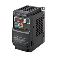
This high performance inverter offers the same usability as the previous model, which allows easy replacement.

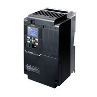
3G3RX2
產品特色
Save energy and maximize performance with versatile inverter
Evolved Heritage
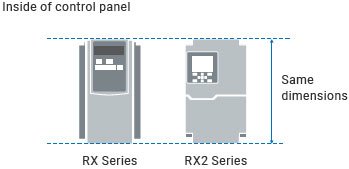
Easy replacement
The RX2 Series with the same mounting dimension as the previous model will fit in the existing control panel or mounting location. In addition, the same setting software CX-Drive can be used for the RX2 Series. Parameter settings and programs used for the previous model can be easily converted and transferred to the RX2 Series.
Note: The depth of some models may vary.
Built-in EMC Filter
Built-in noise filters corresponding to the European EMC Directive IEC61800-3 2nd Environment Category C3 and UL Power Conversion Equipment/UL61800-5-1 will save external hardware and extra cost.

Usability Evolving
The RX2 Series delivers improved usability: more efficient, easier, and faster.
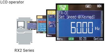
Easy setup and operation
The new full-color LCD operator, which replaced the previous 7-segment display, makes setup and operation more intuitive and easier. The parameter copy function of the operator allows you to quickly copy parameter settings to other RX2 Inverters.
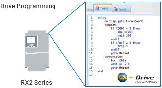
Application customized
The RX2 Inverter can perform simple sequence control programmed using support software CX-Drive.
Crane control, tension control, and other large-scale processes that require fast control speeds can be configured without a PLC, optimizing costs.
In Constant Evolution
The RX2 Series continues to evolve, meeting ever-changing demands and helping improve productivity.
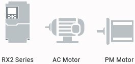
PM motor control
The RX2 Series can control permanent magnet motors (PM motors) as well as induction motors. Auto-tuning maximizes PM motor performance, helping save energy.
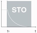
Safety embedded
The RX2 Series features Safe Torque Off (STO) as standard to meet your machine safety needs.
・STO according to IEC 61800-5-2:2016
・PLe and CAT 4 according to EN ISO 13849-1:2015
・SIL3 according to IEC 61508:2010 and EN/IEC 62061:2012
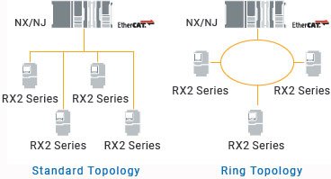
EtherCAT®
The EtherCAT option is available. Connect the RX2 Inverters with the NX/NJ Machine Automation Controller to improve development and production productivity.
Both conf igurations are possible, s tandard and Ring topology.
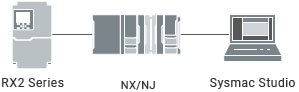
Minimize time to market
One Integrated Development Environment Software.
・ One software to integrate
・ Work as a team
・ Integrated commissioning tools
・ Sysmac troubleshooter
・ Multiple configurations
・ Open Standards
Interpreting Model Numbers
Ordering Information
RX2 series Inverter Models
| Rated voltage | Enclosure ratings | Max. applicable motor capacity | Model | |
|---|---|---|---|---|
| Normal Duty (ND) | Low Duty (LD)/ Very Low Duty (VLD) |
|||
| 3-phase 200 VAC | IP20 | 0.4 kW | 0.75 kW | 3G3RX2-A2004 |
| 0.75 kW | 1.5 kW | 3G3RX2-A2007 | ||
| 1.5 kW | 2.2 kW | 3G3RX2-A2015 | ||
| 2.2 kW | 3.7 kW | 3G3RX2-A2022 | ||
| 3.7 kW | 5.5 kW | 3G3RX2-A2037 | ||
| 5.5 kW | 7.5 kW | 3G3RX2-A2055 | ||
| 7.5 kW | 11 kW | 3G3RX2-A2075 | ||
| 11 kW | 15 kW | 3G3RX2-A2110 | ||
| 15 kW | 18.5 kW | 3G3RX2-A2150 | ||
| 18.5 kW | 22 kW | 3G3RX2-A2185 | ||
| 22 kW | 30 kW | 3G3RX2-A2220 | ||
| 30 kW | 37 kW | 3G3RX2-A2300 | ||
| 37 kW | 45 kW | 3G3RX2-A2370 | ||
| 45 kW | 55 kW | 3G3RX2-A2450 | ||
| 55 kW | 75 kW | 3G3RX2-A2550 | ||
| 3-phase 400 VAC | IP20 | 0.75 kW | 1.5 kW | 3G3RX2-A4007 |
| 1.5 kW | 2.2 kW | 3G3RX2-A4015 | ||
| 2.2 kW | 3.7 kW | 3G3RX2-A4022 | ||
| 3.7 kW | 5.5 kW | 3G3RX2-A4037 | ||
| 5.5 kW | 7.5 kW | 3G3RX2-A4055 | ||
| 7.5 kW | 11 kW | 3G3RX2-A4075 | ||
| 11 kW | 15 kW | 3G3RX2-A4110 | ||
| 15 kW | 18.5 kW | 3G3RX2-A4150 | ||
| 18.5 kW | 22 kW | 3G3RX2-A4185 | ||
| 22 kW | 30 kW | 3G3RX2-A4220 | ||
| 30 kW | 37 kW | 3G3RX2-A4300 | ||
| 37 kW | 45 kW | 3G3RX2-A4370 | ||
| 45 kW | 55 kW | 3G3RX2-A4450 | ||
| 55 kW | 75 kW | 3G3RX2-A4550 | ||
| IP00 | 75 kW | 90 kW | 3G3RX2-B4750 | |
| 90 kW | 110 kW | 3G3RX2-B4900 | ||
| 110 kW | 132 kW | 3G3RX2-B411K | ||
| 132 kW | 160 kW | 3G3RX2-B413K | ||
Communication Unit
| Name | Model |
|---|---|
| EtherCAT Communication Unit | 3G3AX-RX2-ECT |
Related Options
| Name | Specifications | Model | |
|---|---|---|---|
| Regenerative Braking Units |
3-phase 200 VAC | General purpose with Braking resistor | 3G3AX-RBU21 |
| High Regeneration purpose with Braking resistor | 3G3AX-RBU22 | ||
| General purpose for 30 kW * | 3G3AX-RBU23 | ||
| General purpose for 55 kW * | 3G3AX-RBU24 | ||
| 3-phase 400 VAC | General purpose with Braking resistor | 3G3AX-RBU41 | |
| General purpose for 30 kW * | 3G3AX-RBU42 | ||
| General purpose for 55 kW * | 3G3AX-RBU43 | ||
| Braking Resistor | Compact type | Resistor 120 W, 180 Ω | 3G3AX-RBA1201 |
| Resistor 120 W, 100 Ω | 3G3AX-RBA1202 | ||
| Resistor 120 W, 50 Ω | 3G3AX-RBA1203 | ||
| Resistor 120 W, 35 Ω | 3G3AX-RBA1204 | ||
| Standard type | Resistor 200 W, 180 Ω | 3G3AX-RBB2001 | |
| Resistor 200 W, 100 Ω | 3G3AX-RBB2002 | ||
| Resistor 300 W, 50 Ω | 3G3AX-RBB3001 | ||
| Resistor 400 W, 35 Ω | 3G3AX-RBB4001 | ||
| Medium capacity type | Resistor 400 W, 50 Ω | 3G3AX-RBC4001 | |
| Resistor 600 W, 35 Ω | 3G3AX-RBC6001 | ||
| Resistor 1200 W, 17 Ω | 3G3AX-RBC12001 | ||
* The braking resistor is optionally required.
Regenerative Braking Unit and Braking Resistor Combination
Select the combination of the regenerative braking unit(s) and the braking resistor(s) as follows, according to your inverter. If the usage rate exceeds 10% ED, or if you need a torque larger than the approximate braking torque, you need to follow the instruction provided in Braking Resistor Selection.
• Inverter: Select the model of your inverter. The table below assumes that your inverter is used in the heavy load mode and
connected to a single motor with the same capacity. Make sure that the approximate braking torque in the table
shows the assumed value per a motor with the same capacity at ND mode. When using this inverter at LD or VLD
mode, you need to calculate the torque value by dividing VLD by ND.
• Operating conditions: Show the torque during deceleration and the deceleration time (in % ED) calculated as a percentage
of the cycle time for 1 cycle of operation including the stop time.
• Braking unit/Breaking resistor: Show the required the model and number of units.
• Connection form: Show the configuration of the regenerative braking unit(s) and braking resistor(s) illustrated in the
connection form table below.
• Restrictions: Show the maximum deceleration time allowable for the combination shown here and the minimum resistance
that can be connected to the inverter's built-in regenerative braking circuit or external regenerative braking unit(s).

Connection configuration
| Name | Model |
|---|---|
| Radio Noise Filter | 3G3AX-ZCL2 |
| 3G3AX-ZCL1 |
| Name | Inverter | Model | |||||
|---|---|---|---|---|---|---|---|
| Voltage class |
Max. applicable motor capacity [kW] |
Model | Load specification selection |
Max. applicable motor capacity [kW] |
Rated input current [A] |
||
| Input Noise Filter |
200-V class |
0.4 | 3G3RX2-A2004 | ND | 0.4 | 3.3 | 3G3AX-NFI21 |
| LD | 0.75 | 3.9 | |||||
| VLD | 0.75 | 3.9 | |||||
| 0.75 | 3G3RX2-A2007 | ND | 0.75 | 5.5 | |||
| LD | 1.5 | 7.2 | 3G3AX-NFI22 | ||||
| VLD | 1.5 | 7.2 | |||||
| 1.5 | 3G3RX2-A2015 | ND | 1.5 | 8.3 | |||
| LD | 2.2 | 10.8 | 3G3AX-NFI23 | ||||
| VLD | 2.2 | 10.8 | |||||
| 2.2 | 3G3RX2-A2022 | ND | 2.2 | 12 | |||
| LD | 3.7 | 13.9 | |||||
| VLD | 3.7 | 13.9 | |||||
| 3.7 | 3G3RX2-A2037 | ND | 3.7 | 18 | |||
| LD | 5.5 | 23 | 3G3AX-NFI24 | ||||
| VLD | 5.5 | 23 | |||||
| 5.5 | 3G3RX2-A2055 | ND | 5.5 | 26 | |||
| LD | 7.5 | 37 | 3G3AX-NFI25 | ||||
| VLD | 7.5 | 37 | |||||
| 7.5 | 3G3RX2-A2075 | ND | 7.5 | 35 | |||
| LD | 11 | 48 | 3G3AX-NFI26 | ||||
| VLD | 11 | 48 | |||||
| 11 | 3G3RX2-A2110 | ND | 11 | 51 | |||
| LD | 15 | 64 | 3G3AX-NFI27 | ||||
| VLD | 15 | 64 | |||||
| 15 | 3G3RX2-A2150 | ND | 15 | 70 | |||
| LD | 18.5 | 80 | 3G3AX-NFI28 | ||||
| VLD | 18.5 | 80 | |||||
| 18.5 | 3G3RX2-A2185 | ND | 18.5 | 84 | |||
| LD | 22 | 94 | 3G3AX-NFI29 | ||||
| VLD | 22 | 94 | |||||
| 22 | 3G3RX2-A2220 | ND | 22 | 105 | |||
| LD | 30 | 120 | |||||
| VLD | 30 | 120 | |||||
| 30 | 3G3RX2-A2300 | ND | 30 | 133 | |||
| LD | 37 | 150 | 3G3AX-NFI2A | ||||
| VLD | 37 | 150 | |||||
| 37 | 3G3RX2-A2370 | ND | 37 | 160 | |||
| LD | 45 | 186 | 3G3AX-NFI2B | ||||
| VLD | 45 | 186 | |||||
| 45 | 3G3RX2-A2450 | ND | 45 | 200 | |||
| LD | 55 | 240 | 3G3AX-NFI2C | ||||
| VLD | 55 | 240 | |||||
| 55 | 3G3RX2-A2550 | ND | 55 | 242 | |||
| LD | 75 | 280 | --- | ||||
| VLD | 75 | 280 | |||||
| 400-V class |
0.75 | 3G3RX2-A4007 | ND | 0.75 | 2.8 | 3G3AX-NFI41 | |
| LD | 1.5 | 4.3 | |||||
| VLD | 1.5 | 4.3 | |||||
| 1.5 | 3G3RX2-A4015 | ND | 1.5 | 4.2 | |||
| LD | 2.2 | 5.9 | |||||
| VLD | 2.2 | 5.9 | |||||
| 2.2 | 3G3RX2-A4022 | ND | 2.2 | 5.8 | |||
| LD | 3.7 | 8.1 | 3G3AX-NFI42 | ||||
| VLD | 3.7 | 8.1 | |||||
| 3.7 | 3G3RX2-A4037 | ND | 3.7 | 9.8 | |||
| LD | 5.5 | 13.3 | 3G3AX-NFI43 | ||||
| VLD | 5.5 | 13.3 | |||||
| 5.5 | 3G3RX2-A4055 | ND | 5.5 | 15 | |||
| LD | 7.5 | 20 | |||||
| VLD | 7.5 | 20 | |||||
| 7.5 | 3G3RX2-A4075 | ND | 7.5 | 21 | |||
| LD | 11 | 24 | 3G3AX-NFI44 | ||||
| VLD | 11 | 24 | |||||
| 11 | 3G3RX2-A4110 | ND | 11 | 28 | |||
| LD | 15 | 32 | 3G3AX-NFI45 | ||||
| VLD | 15 | 32 | |||||
| 15 | 3G3RX2-A4150 | ND | 15 | 35 | |||
| LD | 18.5 | 41 | 3G3AX-NFI46 | ||||
| VLD | 18.5 | 41 | |||||
| 18.5 | 3G3RX2-A4185 | ND | 18.5 | 42 | |||
| LD | 22 | 47 | 3G3AX-NFI47 | ||||
| VLD | 22 | 47 | |||||
| 22 | 3G3RX2-A4220 | ND | 22 | 53 | |||
| LD | 30 | 63 | 3G3AX-NFI48 | ||||
| VLD | 30 | 63 | |||||
| 30 | 3G3RX2-A4300 | ND | 30 | 64 | |||
| LD | 37 | 77 | 3G3AX-NFI49 | ||||
| VLD | 37 | 77 | |||||
| 37 | 3G3RX2-A4370 | ND | 37 | 83 | |||
| LD | 45 | 94 | 3G3AX-NFI4A | ||||
| VLD | 45 | 94 | |||||
| 45 | 3G3RX2-A4450 | ND | 45 | 100 | |||
| LD | 55 | 116 | |||||
| VLD | 55 | 116 | |||||
| 55 | 3G3RX2-A4550 | ND | 55 | 121 | |||
| LD | 75 | 149 | --- | ||||
| VLD | 75 | 149 | |||||
| Name | Inverter | Model | |||||
|---|---|---|---|---|---|---|---|
| Voltage class |
Max. applicable motor capacity [kW] |
Model | Load specification selection |
Max. applicable motor capacity [kW] |
Rated input current [A] |
||
| EMC Noise Filter * |
200-V class |
0.4 | 3G3RX2-A2004 | ND | 0.4 | 3.3 | 3G3AX-EFI41 |
| LD | 0.75 | 3.9 | |||||
| VLD | 0.75 | 3.9 | |||||
| 0.75 | 3G3RX2-A2007 | ND | 0.75 | 5.5 | |||
| LD | 1.5 | 7.2 | 3G3AX-EFI42 | ||||
| VLD | 1.5 | 7.2 | |||||
| 1.5 | 3G3RX2-A2015 | ND | 1.5 | 8.3 | |||
| LD | 2.2 | 10.8 | 3G3AX-EFI43 | ||||
| VLD | 2.2 | 10.8 | |||||
| 2.2 | 3G3RX2-A2022 | ND | 2.2 | 12 | |||
| LD | 3.7 | 13.9 | |||||
| VLD | 3.7 | 13.9 | |||||
| 3.7 | 3G3RX2-A2037 | ND | 3.7 | 18 | |||
| LD | 5.5 | 23 | 3G3AX-EFI44 | ||||
| VLD | 5.5 | 23 | |||||
| 5.5 | 3G3RX2-A2055 | ND | 5.5 | 26 | |||
| LD | 7.5 | 37 | 3G3AX-EFI45 | ||||
| VLD | 7.5 | 37 | |||||
| 7.5 | 3G3RX2-A2075 | ND | 7.5 | 35 | |||
| LD | 11 | 48 | 3G3AX-EFI47 | ||||
| VLD | 11 | 48 | |||||
| 11 | 3G3RX2-A2110 | ND | 11 | 51 | |||
| LD | 15 | 64 | 3G3AX-EFI48 | ||||
| VLD | 15 | 64 | |||||
| 15 | 3G3RX2-A2150 | ND | 15 | 70 | |||
| LD | 18.5 | 80 | 3G3AX-EFI49 | ||||
| VLD | 18.5 | 80 | |||||
| 18.5 | 3G3RX2-A2185 | ND | 18.5 | 84 | |||
| LD | 22 | 94 | 3G3AX-EFI4A | ||||
| VLD | 22 | 94 | |||||
| 22 | 3G3RX2-A2220 | ND | 22 | 105 | |||
| LD | 30 | 120 | |||||
| VLD | 30 | 120 | |||||
| 30 | 3G3RX2-A2300 | ND | 30 | 133 | |||
| LD | 37 | 150 | 3G3AX-EFI4B | ||||
| VLD | 37 | 150 | |||||
| 37 | 3G3RX2-A2370 | ND | 37 | 160 | |||
| LD | 45 | 186 | --- | ||||
| VLD | 45 | 186 | |||||
| 400-V class |
0.75 | 3G3RX2-A4007 | ND | 0.75 | 2.8 | 3G3AX-EFI41 | |
| LD | 1.5 | 4.3 | |||||
| VLD | 1.5 | 4.3 | |||||
| 1.5 | 3G3RX2-A4015 | ND | 1.5 | 4.2 | |||
| LD | 2.2 | 5.9 | |||||
| VLD | 2.2 | 5.9 | |||||
| 2.2 | 3G3RX2-A4022 | ND | 2.2 | 5.8 | |||
| LD | 3.7 | 8.1 | 3G3AX-EFI42 | ||||
| VLD | 3.7 | 8.1 | |||||
| 3.7 | 3G3RX2-A4037 | ND | 3.7 | 9.8 | |||
| LD | 5.5 | 13.3 | 3G3AX-EFI43 | ||||
| VLD | 5.5 | 13.3 | |||||
| 5.5 | 3G3RX2-A4055 | ND | 5.5 | 15 | |||
| LD | 7.5 | 20 | |||||
| VLD | 7.5 | 20 | |||||
| 7.5 | 3G3RX2-A4075 | ND | 7.5 | 21 | |||
| LD | 11 | 24 | 3G3AX-EFI44 | ||||
| VLD | 11 | 24 | |||||
| 11 | 3G3RX2-A4110 | ND | 11 | 28 | |||
| LD | 15 | 32 | 3G3AX-EFI45 | ||||
| VLD | 15 | 32 | |||||
| 15 | 3G3RX2-A4150 | ND | 15 | 35 | |||
| LD | 18.5 | 41 | 3G3AX-EFI46 | ||||
| VLD | 18.5 | 41 | |||||
| 18.5 | 3G3RX2-A4185 | ND | 18.5 | 42 | |||
| LD | 22 | 47 | 3G3AX-EFI47 | ||||
| VLD | 22 | 47 | |||||
| 22 | 3G3RX2-A4220 | ND | 22 | 53 | |||
| LD | 30 | 63 | 3G3AX-EFI48 | ||||
| VLD | 30 | 63 | |||||
| 30 | 3G3RX2-A4300 | ND | 30 | 64 | |||
| LD | 37 | 77 | 3G3AX-EFI49 | ||||
| VLD | 37 | 77 | |||||
| 37 | 3G3RX2-A4370 | ND | 37 | 83 | |||
| LD | 45 | 94 | 3G3AX-EFI4A | ||||
| VLD | 45 | 94 | |||||
| 45 | 3G3RX2-A4450 | ND | 45 | 100 | |||
| LD | 55 | 116 | |||||
| VLD | 55 | 116 | |||||
| 55 | 3G3RX2-A4550 | ND | 55 | 121 | |||
| LD | 75 | 149 | 3G3AX-EFI4B | ||||
| VLD | 75 | 149 | |||||
| 75 | 3G3RX2-B4750 | ND | 75 | 164 | |||
| LD | 90 | 176 | |||||
| VLD | 90 | 176 | |||||
| 90 | 3G3RX2-B4900 | ND | 90 | 194 | |||
| LD | 110 | 199 | --- | ||||
| VLD | 110 | 199 | |||||
* Although an EMC Noise Filter is built into the RX2, it may be necessary to provide another EMC Noise Filter when the
cable between the Motor and the Inverter is long.
cable between the Motor and the Inverter is long.
| Name | Inverter | Model | |||||
|---|---|---|---|---|---|---|---|
| Voltage class |
Max. applicable motor capacity [kW] |
Model | Load specification selection |
Max. applicable motor capacity [kW] |
Rated input current [A] |
||
| Output Noise Filter |
200-V class |
0.4 | 3G3RX2-A2004 | ND | 0.4 | 3 | 3G3AX-NFO01 |
| LD | 0.75 | 3.7 | |||||
| VLD | 0.75 | 3.7 | |||||
| 0.75 | 3G3RX2-A2007 | ND | 0.75 | 5 | |||
| LD | 1.5 | 6.3 | 3G3AX-NFO02 | ||||
| VLD | 1.5 | 6.3 | |||||
| 1.5 | 3G3RX2-A2015 | ND | 1.5 | 7.5 | |||
| LD | 2.2 | 9.4 | |||||
| VLD | 2.2 | 9.4 | |||||
| 2.2 | 3G3RX2-A2022 | ND | 2.2 | 10.5 | |||
| LD | 3.7 | 12 | 3G3AX-NFO03 | ||||
| VLD | 3.7 | 12 | |||||
| 3.7 | 3G3RX2-A2037 | ND | 3.7 | 16.5 | |||
| LD | 5.5 | 19.6 | |||||
| VLD | 5.5 | 19.6 | |||||
| 5.5 | 3G3RX2-A2055 | ND | 5.5 | 24 | |||
| LD | 7.5 | 30 | 3G3AX-NFO04 | ||||
| VLD | 7.5 | 30 | |||||
| 7.5 | 3G3RX2-A2075 | ND | 7.5 | 32 | |||
| LD | 11 | 44 | |||||
| VLD | 11 | 44 | |||||
| 11 | 3G3RX2-A2110 | ND | 11 | 46 | |||
| LD | 15 | 58 | 3G3AX-NFO05 | ||||
| VLD | 15 | 58 | |||||
| 15 | 3G3RX2-A2150 | ND | 15 | 64 | |||
| LD | 18.5 | 73 | 3G3AX-NFO06 | ||||
| VLD | 18.5 | 73 | |||||
| 18.5 | 3G3RX2-A2185 | ND | 18.5 | 76 | |||
| LD | 22 | 85 | |||||
| VLD | 22 | 85 | |||||
| 22 | 3G3RX2-A2220 | ND | 22 | 95 | |||
| LD | 30 | 113 | 3G3AX-NFO07 | ||||
| VLD | 30 | 113 | |||||
| 30 | 3G3RX2-A2300 | ND | 30 | 121 | |||
| LD | 37 | 140 | |||||
| VLD | 37 | 140 | |||||
| 37 | 3G3RX2-A2370 | ND | 37 | 145 | |||
| LD | 45 | 169 | --- | ||||
| VLD | 45 | 169 | |||||
| 400-V class |
0.75 | 3G3RX2-A4007 | ND | 0.75 | 2.5 | 3G3AX-NFO01 | |
| LD | 1.5 | 3.1 | |||||
| VLD | 1.5 | 3.1 | |||||
| 1.5 | 3G3RX2-A4015 | ND | 1.5 | 3.8 | |||
| LD | 2.2 | 4.8 | |||||
| VLD | 2.2 | 4.8 | |||||
| 2.2 | 3G3RX2-A4022 | ND | 2.2 | 5.3 | |||
| LD | 3.7 | 6.7 | 3G3AX-NFO02 | ||||
| VLD | 3.7 | 6.7 | |||||
| 3.7 | 3G3RX2-A4037 | ND | 3.7 | 9 | |||
| LD | 5.5 | 11.1 | 3G3AX-NFO03 | ||||
| VLD | 5.5 | 11.1 | |||||
| 5.5 | 3G3RX2-A4055 | ND | 5.5 | 14 | |||
| LD | 7.5 | 16 | |||||
| VLD | 7.5 | 16 | |||||
| 7.5 | 3G3RX2-A4075 | ND | 7.5 | 19 | |||
| LD | 11 | 22 | |||||
| VLD | 11 | 22 | |||||
| 11 | 3G3RX2-A4110 | ND | 11 | 25 | |||
| LD | 15 | 29 | 3G3AX-NFO04 | ||||
| VLD | 15 | 29 | |||||
| 15 | 3G3RX2-A4150 | ND | 15 | 32 | |||
| LD | 18.5 | 37 | |||||
| VLD | 18.5 | 37 | |||||
| 18.5 | 3G3RX2-A4185 | ND | 18.5 | 38 | |||
| LD | 22 | 43 | |||||
| VLD | 22 | 43 | |||||
| 22 | 3G3RX2-A4220 | ND | 22 | 48 | |||
| LD | 30 | 57 | 3G3AX-NFO05 | ||||
| VLD | 30 | 57 | |||||
| 30 | 3G3RX2-A4300 | ND | 30 | 58 | |||
| LD | 37 | 70 | |||||
| VLD | 37 | 70 | |||||
| 37 | 3G3RX2-A4370 | ND | 37 | 75 | |||
| LD | 45 | 85 | 3G3AX-NFO06 | ||||
| VLD | 45 | 85 | |||||
| 45 | 3G3RX2-A4450 | ND | 45 | 91 | |||
| LD | 55 | 105 | 3G3AX-NFO07 | ||||
| VLD | 55 | 105 | |||||
| 55 | 3G3RX2-A4550 | ND | 55 | 112 | |||
| LD | 75 | 135 | |||||
| VLD | 75 | 135 | |||||
| 75 | 3G3RX2-B4750 | ND | 75 | 149 | |||
| LD | 90 | 160 | --- | ||||
| VLD | 90 | 160 | |||||
| Name | Inverter | Model | |||||
|---|---|---|---|---|---|---|---|
| Voltage class |
Max. applicable motor capacity [kW] |
Model | Load specification selection |
Max. applicable motor capacity [kW] |
Rated input current [A] |
||
| DC Reactor |
200-V class |
0.4 | 3G3RX2-A2004 | ND | 0.4 | 3.3 | 3G3AX-DL2004 |
| LD | 0.75 | 3.9 | 3G3AX-DL2007 | ||||
| VLD | 0.75 | 3.9 | |||||
| 0.75 | 3G3RX2-A2007 | ND | 0.75 | 5.5 | |||
| LD | 1.5 | 7.2 | 3G3AX-DL2015 | ||||
| VLD | 1.5 | 7.2 | |||||
| 1.5 | 3G3RX2-A2015 | ND | 1.5 | 8.3 | |||
| LD | 2.2 | 10.8 | 3G3AX-DL2022 | ||||
| VLD | 2.2 | 10.8 | |||||
| 2.2 | 3G3RX2-A2022 | ND | 2.2 | 12 | |||
| LD | 3.7 | 13.9 | 3G3AX-DL2037 | ||||
| VLD | 3.7 | 13.9 | |||||
| 3.7 | 3G3RX2-A2037 | ND | 3.7 | 18 | |||
| LD | 5.5 | 23 | 3G3AX-DL2055 | ||||
| VLD | 5.5 | 23 | |||||
| 5.5 | 3G3RX2-A2055 | ND | 5.5 | 26 | |||
| LD | 7.5 | 37 | 3G3AX-DL2075 | ||||
| VLD | 7.5 | 37 | |||||
| 7.5 | 3G3RX2-A2075 | ND | 7.5 | 35 | |||
| LD | 11 | 48 | 3G3AX-DL2110 | ||||
| VLD | 11 | 48 | |||||
| 11 | 3G3RX2-A2110 | ND | 11 | 51 | |||
| LD | 15 | 64 | 3G3AX-DL2150 | ||||
| VLD | 15 | 64 | |||||
| 15 | 3G3RX2-A2150 | ND | 15 | 70 | |||
| LD | 18.5 | 80 | 3G3AX-DL2220 | ||||
| VLD | 18.5 | 80 | |||||
| 18.5 | 3G3RX2-A2185 | ND | 18.5 | 84 | |||
| LD | 22 | 94 | |||||
| VLD | 22 | 94 | |||||
| 22 | 3G3RX2-A2220 | ND | 22 | 105 | |||
| LD | 30 | 120 | 3G3AX-DL2300 | ||||
| VLD | 30 | 120 | |||||
| 30 | 3G3RX2-A2300 | ND | 30 | 133 | |||
| LD | 37 | 150 | 3G3AX-DL2370 | ||||
| VLD | 37 | 150 | |||||
| 37 | 3G3RX2-A2370 | ND | 37 | 160 | |||
| LD | 45 | 186 | 3G3AX-DL2450 | ||||
| VLD | 45 | 186 | |||||
| 45 | 3G3RX2-A2450 | ND | 45 | 200 | |||
| LD | 55 | 240 | 3G3AX-DL2550 | ||||
| VLD | 55 | 240 | |||||
| 55 | 3G3RX2-A2550 | ND | 55 | 242 | |||
| LD | 75 | 280 | --- | ||||
| VLD | 75 | 280 | |||||
| 400-V class |
0.75 | 3G3RX2-A4007 | ND | 0.75 | 2.8 | 3G3AX-DL4007 | |
| LD | 1.5 | 4.3 | 3G3AX-DL4015 | ||||
| VLD | 1.5 | 4.3 | |||||
| 1.5 | 3G3RX2-A4015 | ND | 1.5 | 4.2 | |||
| LD | 2.2 | 5.9 | 3G3AX-DL4022 | ||||
| VLD | 2.2 | 5.9 | |||||
| 2.2 | 3G3RX2-A4022 | ND | 2.2 | 5.8 | |||
| LD | 3.7 | 8.1 | 3G3AX-DL4037 | ||||
| VLD | 3.7 | 8.1 | |||||
| 3.7 | 3G3RX2-A4037 | ND | 3.7 | 9.8 | |||
| LD | 5.5 | 13.3 | 3G3AX-DL4055 | ||||
| VLD | 5.5 | 13.3 | |||||
| 5.5 | 3G3RX2-A4055 | ND | 5.5 | 15 | |||
| LD | 7.5 | 20 | 3G3AX-DL4075 | ||||
| VLD | 7.5 | 20 | |||||
| 7.5 | 3G3RX2-A4075 | ND | 7.5 | 21 | |||
| LD | 11 | 24 | 3G3AX-DL4110 | ||||
| VLD | 11 | 24 | |||||
| 11 | 3G3RX2-A4110 | ND | 11 | 28 | |||
| LD | 15 | 32 | 3G3AX-DL4150 | ||||
| VLD | 15 | 32 | |||||
| 15 | 3G3RX2-A4150 | ND | 15 | 35 | |||
| LD | 18.5 | 41 | 3G3AX-DL4220 | ||||
| VLD | 18.5 | 41 | |||||
| 18.5 | 3G3RX2-A4185 | ND | 18.5 | 42 | |||
| LD | 22 | 47 | |||||
| VLD | 22 | 47 | |||||
| 22 | 3G3RX2-A4220 | ND | 22 | 53 | |||
| LD | 30 | 63 | 3G3AX-DL4300 | ||||
| VLD | 30 | 63 | |||||
| 30 | 3G3RX2-A4300 | ND | 30 | 64 | |||
| LD | 37 | 77 | 3G3AX-DL4370 | ||||
| VLD | 37 | 77 | |||||
| 37 | 3G3RX2-A4370 | ND | 37 | 83 | |||
| LD | 45 | 94 | 3G3AX-DL4450 | ||||
| VLD | 45 | 94 | |||||
| 45 | 3G3RX2-A4450 | ND | 45 | 100 | |||
| LD | 55 | 116 | 3G3AX-DL4550 | ||||
| VLD | 55 | 116 | |||||
| 55 | 3G3RX2-A4550 | ND | 55 | 121 | |||
| LD | 75 | 149 | --- | ||||
| VLD | 75 | 149 | |||||
| Name | Inverter | Model | |||||
|---|---|---|---|---|---|---|---|
| Voltage class |
Max. applicable motor capacity [kW] |
Model | Load specification selection |
Max. applicable motor capacity [kW] |
Rated input current [A] |
||
| AC Reactor |
200-V class |
0.4 | 3G3RX2-A2004 | ND | 0.4 | 3.3 | 3G3AX-AL2025 |
| LD | 0.75 | 3.9 | |||||
| VLD | 0.75 | 3.9 | |||||
| 0.75 | 3G3RX2-A2007 | ND | 0.75 | 5.5 | |||
| LD | 1.5 | 7.2 | |||||
| VLD | 1.5 | 7.2 | |||||
| 1.5 | 3G3RX2-A2015 | ND | 1.5 | 8.3 | |||
| LD | 2.2 | 10.8 | 3G3AX-AL2055 | ||||
| VLD | 2.2 | 10.8 | |||||
| 2.2 | 3G3RX2-A2022 | ND | 2.2 | 12 | |||
| LD | 3.7 | 13.9 | |||||
| VLD | 3.7 | 13.9 | |||||
| 3.7 | 3G3RX2-A2037 | ND | 3.7 | 18 | |||
| LD | 5.5 | 23 | 3G3AX-AL2110 | ||||
| VLD | 5.5 | 23 | |||||
| 5.5 | 3G3RX2-A2055 | ND | 5.5 | 26 | |||
| LD | 7.5 | 37 | |||||
| VLD | 7.5 | 37 | |||||
| 7.5 | 3G3RX2-A2075 | ND | 7.5 | 35 | |||
| LD | 11 | 48 | 3G3AX-AL2220 | ||||
| VLD | 11 | 48 | |||||
| 11 | 3G3RX2-A2110 | ND | 11 | 51 | |||
| LD | 15 | 64 | |||||
| VLD | 15 | 64 | |||||
| 15 | 3G3RX2-A2150 | ND | 15 | 70 | |||
| LD | 18.5 | 80 | 3G3AX-AL2330 | ||||
| VLD | 18.5 | 80 | |||||
| 18.5 | 3G3RX2-A2185 | ND | 18.5 | 84 | |||
| LD | 22 | 94 | |||||
| VLD | 22 | 94 | |||||
| 22 | 3G3RX2-A2220 | ND | 22 | 105 | |||
| LD | 30 | 120 | 3G3AX-AL2500 | ||||
| VLD | 30 | 120 | |||||
| 30 | 3G3RX2-A2300 | ND | 30 | 133 | |||
| LD | 37 | 150 | |||||
| VLD | 37 | 150 | |||||
| 37 | 3G3RX2-A2370 | ND | 37 | 160 | |||
| LD | 45 | 186 | 3G3AX-AL2750 | ||||
| VLD | 45 | 186 | |||||
| 45 | 3G3RX2-A2450 | ND | 45 | 200 | |||
| LD | 55 | 240 | |||||
| VLD | 55 | 240 | |||||
| 55 | 3G3RX2-A2550 | ND | 55 | 242 | |||
| LD | 75 | 280 | --- | ||||
| VLD | 75 | 280 | |||||
| 400-V class |
0.75 | 3G3RX2-A4007 | ND | 0.75 | 2.8 | 3G3AX-AL4025 | |
| LD | 1.5 | 4.3 | |||||
| VLD | 1.5 | 4.3 | |||||
| 1.5 | 3G3RX2-A4015 | ND | 1.5 | 4.2 | |||
| LD | 2.2 | 5.9 | 3G3AX-AL4055 | ||||
| VLD | 2.2 | 5.9 | |||||
| 2.2 | 3G3RX2-A4022 | ND | 2.2 | 5.8 | |||
| LD | 3.7 | 8.1 | |||||
| VLD | 3.7 | 8.1 | |||||
| 3.7 | 3G3RX2-A4037 | ND | 3.7 | 9.8 | |||
| LD | 5.5 | 13.3 | 3G3AX-AL4110 | ||||
| VLD | 5.5 | 13.3 | |||||
| 5.5 | 3G3RX2-A4055 | ND | 5.5 | 15 | |||
| LD | 7.5 | 20 | |||||
| VLD | 7.5 | 20 | |||||
| 7.5 | 3G3RX2-A4075 | ND | 7.5 | 21 | |||
| LD | 11 | 24 | 3G3AX-AL4220 | ||||
| VLD | 11 | 24 | |||||
| 11 | 3G3RX2-A4110 | ND | 11 | 28 | |||
| LD | 15 | 32 | |||||
| VLD | 15 | 32 | |||||
| 15 | 3G3RX2-A4150 | ND | 15 | 35 | |||
| LD | 18.5 | 41 | 3G3AX-AL4330 | ||||
| VLD | 18.5 | 41 | |||||
| 18.5 | 3G3RX2-A4185 | ND | 18.5 | 42 | |||
| LD | 22 | 47 | |||||
| VLD | 22 | 47 | |||||
| 22 | 3G3RX2-A4220 | ND | 22 | 53 | |||
| LD | 30 | 63 | 3G3AX-AL4500 | ||||
| VLD | 30 | 63 | |||||
| 30 | 3G3RX2-A4300 | ND | 30 | 64 | |||
| LD | 37 | 77 | |||||
| VLD | 37 | 77 | |||||
| 37 | 3G3RX2-A4370 | ND | 37 | 83 | |||
| LD | 45 | 94 | 3G3AX-AL4750 | ||||
| VLD | 45 | 94 | |||||
| 45 | 3G3RX2-A4450 | ND | 45 | 100 | |||
| LD | 55 | 116 | |||||
| VLD | 55 | 116 | |||||
| 55 | 3G3RX2-A4550 | ND | 55 | 121 | |||
| LD | 75 | 149 | --- | ||||
| VLD | 75 | 149 | |||||
| Name | Specifications | Model |
|---|---|---|
| PG Option Unit | For Position or Frequency Control | 3G3AX-RX2-PG01 |
| Digital Operator Connecting Cable |
RJ45 connector, EIA568-compliant cable (UTP category 5), Cable Length 1 m | 3G3AX-OPCN1 |
| RJ45 connector, EIA568-compliant cable (UTP category 5), Cable Length 3 m | 3G3AX-OPCN3 |
Recommended EtherCAT Communications Cables
Use a straight STP (shielded twisted-pair) cable of category 5 or higher with double shielding (aluminum tape and braiding) for EtherCAT.
Cable with Connectors
| Item | Recommended manufacturer |
Cable length (m) |
Model | |
|---|---|---|---|---|
| Wire gauge and number of pairs: AWG26, 4-pair cable Cable sheath material: LSZH *1 |
Cable with Connectors on Both Ends (RJ45/RJ45) Standard RJ45 plugs *2 Cable color: Yellow *3  |
OMRON | 0.3 | XS6W-6LSZH8SS30CM-Y |
| 0.5 | XS6W-6LSZH8SS50CM-Y | |||
| 1 | XS6W-6LSZH8SS100CM-Y | |||
| 2 | XS6W-6LSZH8SS200CM-Y | |||
| 3 | XS6W-6LSZH8SS300CM-Y | |||
| 5 | XS6W-6LSZH8SS500CM-Y | |||
| Wire gauge and number of pairs: AWG22, 2-pair cable |
Cable with Connectors on Both Ends (RJ45/RJ45) Rugged RJ45 plugs *2 Cable color: Light blue  |
OMRON | 0.3 | XS5W-T421-AMD-K |
| 0.5 | XS5W-T421-BMD-K | |||
| 1 | XS5W-T421-CMD-K | |||
| 2 | XS5W-T421-DMD-K | |||
| 5 | XS5W-T421-GMD-K | |||
| 10 | XS5W-T421-JMD-K | |||
| Cable with Connectors on Both Ends (M12 Straight/RJ45) Shield strengthening connector cable *4 M12/Smartclick connector and rugged RJ45 plug Cable color: Black  |
OMRON | 0.5 | XS5W-T421-BMC-SS | |
| 1 | XS5W-T421-CMC-SS | |||
| 2 | XS5W-T421-DMC-SS | |||
| 3 | XS5W-T421-EMC-SS | |||
| 5 | XS5W-T421-GMC-SS | |||
| 10 | XS5W-T421-JMC-SS | |||
*1. The lineup features Low Smoke Zero Halogen cables for in-cabinet use and PUR cables for out-of-cabinet use. Although
the LSZH cable is single shielded, its communications and noise characteristics meet the standards.
*2. Cables with standard RJ45 plugs are available in the following lengths: 0.2 m, 0.3 m, 0.5 m, 1 m, 1.5 m, 2 m, 3 m, 5 m,
7.5 m, 10 m, 15 m, 20 m.
Cables with rugged RJ45 plugs are available in the following lengths: 0.3 m, 0.5 m, 1 m, 2 m, 3 m, 5 m, 10 m, 15 m.
For details, refer to the Industrial Ethernet Connectors Catalog (Cat. No. G019).
*3. Cable colors are available in yellow, green, and blue.
*4. For details, contact your OMRON representative.
Cables/Connectors
| Item | Recommended manufacturer |
Model | |
|---|---|---|---|
| Wire gauge and number of pairs: AWG24, 4-pair cable |
Cable | Hitachi Metals, Ltd. | NETSTAR-C5E SAB0.5×4P CP *1 |
| Kuramo Electric Co. | KETH-SB *1 | ||
| RJ45 Connector | Panduit Corporation | MPS588-C *1 | |
| Wire gauge and number of pairs: AWG22, 2-pair cable |
Cable | Kuramo Electric Co. | KETH-PSB-OMR *2 |
| JMACS Japan Co., Ltd. | PNET/B *2 | ||
| RJ45 Assembly Connector  |
OMRON | XS6G-T421-1 *2 | |
*1. We recommend you to use the above Cable and RJ45 Connector together.
*2. We recommend you to use the above Cable and RJ45 Assembly Connector together.
Software
How to Select Required Support Software for Your Controller
The required Support Software depends on the Controller to connect. Please check the following table when purchasing the Support Software.
| Item | Omron PLC System | Omron Machine Automation Controller System |
|---|---|---|
| Controller | CS, CJ, CP, and other series | NJ series |
| Inverter | Inverter RX2-series | Inverter RX2-series with EtherCAT Communication Unit 3G3AX-RX2-ECT |
| Software | FA Integrated Tool Package CX-One (CX-Drive: Version 3.00 or higher) |
Automation Software Sysmac Studio (Version 1.47 or higher) |
FA Integrated Tool Package CX-One
| Product name |
Specifications | Model | ||
|---|---|---|---|---|
| Number of licenses |
Media | |||
| FA Integrated Tool Package CX-One Ver.4.[] |
The CX-One is a comprehensive software package that integrates Support Software for OMRON PLCs and components. CX-One runs on the following OS. Windows 7 (32-bit/64-bit version) / Windows 8 (32-bit/64- bit version) /Windows 8.1 (32-bit/64-bit version) / Windows 10 (32-bit/64-bit version) CX-One Version 4.[] includes CX-Drive Ver.3.[]. For details, refer to your local OMRON website. |
1 license *1 |
DVD *2 |
CXONE-AL01D-V4 |
*1. Multi licenses are available for the CX-One (3, 10, 30, or 50 licenses).
Note: The RX2-series is supported by CX-Drive version 3.00 or higher.
Automation Software Sysmac Studio
Please purchase a DVD and required number of licenses the first time you purchase the Sysmac Studio. DVDs and licenses are available individually. Each model of licenses does not include any DVD.
| Product name |
Specifications | Model | ||
|---|---|---|---|---|
| Number of licenses |
Media | |||
| Sysmac Studio Standard Edition Ver.1.[][] *1 |
The Sysmac Studio is the software that provides an integrated environment for setting, programming, debugging and maintenance of machine automation controllers including NJ/NX-series CPU Units, NY-series Industrial PC, EtherCAT Slaves, and HMI. Sysmac Studio runs on the following OS. Windows 7 (32-bit/64-bit version)/Windows 8 (32-bit/64-bit version)/Windows 8.1 (32-bit/64-bit version)/Windows 10 (32-bit/64-bit version) *1 The Sysmac Studio Standard Edition DVD includes Support Software to set up EtherNet/IP Units, DeviceNet slaves, Serial Communications Units, and Support Software for creating screens on HMIs (CX-Designer). For details, refer to your local OMRON website. |
--- (Media only) |
Sysmac Studio (32 bit) DVD |
SYSMAC-SE200D |
| --- (Media only) |
Sysmac Studio (64 bit) DVD |
SYSMAC-SE200D-64 | ||
| 1 license *2 |
--- | SYSMAC-SE201L | ||
*1. Model "SYSMAC-SE200D-64" runs on Windows 10 (64 bit).
*2. Multi licenses are available for the Sysmac Studio (3, 10, 30, or 50 licenses).
Note: The RX-series with EtherCAT Communication Unit 3G3AX-RX2-ECT version 1.0 or later is supported by Sysmac
Studio version 1.47 or higher.
*2. Multi licenses are available for the Sysmac Studio (3, 10, 30, or 50 licenses).
Note: The RX-series with EtherCAT Communication Unit 3G3AX-RX2-ECT version 1.0 or later is supported by Sysmac
Studio version 1.47 or higher.
Performance Specifications
Inverter 3G3RX2
3-phase 200-V Class
Very Low Duty (VLD)/Low Duty (LD)/Normal Duty (ND)
| 3G3RX2-A2[][][][][] | A2004 | A2007 | A2015 | A2022 | A2037 | |||
|---|---|---|---|---|---|---|---|---|
| Applicable motor (4-pole) capacity (kW) |
VLD | 0.75 | 1.5 | 2.2 | 3.7 | 5.5 | ||
| LD | 0.75 | 1.5 | 2.2 | 3.7 | 5.5 | |||
| ND | 0.4 | 0.75 | 1.5 | 2.2 | 3.7 | |||
| Output | Rated output current (A) |
VLD | 4.4 | 8.0 | 10.4 | 15.6 | 22.8 | |
| LD | 3.7 | 6.3 | 9.4 | 12.0 | 19.6 | |||
| ND | 3.2 | 5.0 | 8.0 | 11.0 | 17.5 | |||
| Overload current rating |
VLD | 110% 60 sec / 120% 3 sec | ||||||
| LD | 120% 60 sec / 150% 3 sec | |||||||
| ND | 150% 60 sec / 200% 3 sec | |||||||
| Rated output voltage | 3-phase (3-wire) 200 to 240 V (depending on receiving voltage) | |||||||
| Rated capacity (kVA) |
200 V | VLD | 1.5 | 2.8 | 3.6 | 5.4 | 7.9 | |
| LD | 1.3 | 2.2 | 3.3 | 4.2 | 6.8 | |||
| ND | 1.1 | 1.7 | 2.8 | 3.8 | 6.1 | |||
| 240 V | VLD | 1.8 | 3.3 | 4.3 | 6.5 | 9.5 | ||
| LD | 1.5 | 2.6 | 3.9 | 5.0 | 8.1 | |||
| ND | 1.3 | 2.1 | 3.3 | 4.6 | 7.3 | |||
| Input | Rated input current (A) *1 |
VLD | 5.2 | 9.5 | 12.4 | 18.6 | 27.1 | |
| LD | 4.4 | 7.5 | 11.2 | 14.3 | 23.3 | |||
| ND | 3.8 | 6.0 | 9.5 | 13.1 | 20.8 | |||
| Rated input AC voltage | Control power supply: Power supply single phase 200 to 240 V/allowable variation range 170 to 264 V, 50 Hz (allowable variation range: 47.5 to 52.5 Hz)/60 Hz (allowable variation range: 57 to 63 Hz) |
|||||||
| Main circuit power supply: 3-phase (3-wire) 200 to 240 V/allowable variation range 170 to 264 V, 50 Hz (allowable variation range: 47.5 to 52.5 Hz)/60 Hz (allowable variation range: 57 to 63 Hz) |
||||||||
| Power supply equipment capacity (kVA) *2 |
VLD | 2.0 | 3.6 | 4.7 | 7.1 | 10.3 | ||
| LD | 1.7 | 2.9 | 4.3 | 5.4 | 8.9 | |||
| ND | 1.5 | 2.3 | 3.6 | 5.0 | 7.9 | |||
| Carrier frequency operating range *3 |
VLD | 0.5 to 10.0 kHz | ||||||
| LD | 0.5 to 12.0 kHz | |||||||
| ND | 0.5 to 16.0 kHz | |||||||
| Motor start torque *4 | 200%/0.3 Hz | |||||||
| Braking | Regenerative braking | Equipped with BRD circuit (with a discharging resistor separately installed) | ||||||
| Minimum resistance that can be connected (Ω) |
50 | 50 | 35 | 35 | 35 | |||
| Dimension | Height (mm) | 255 | 255 | 255 | 255 | 255 | ||
| Width (mm) | 150 | 150 | 150 | 150 | 150 | |||
| Depth (mm) | 140 | 140 | 140 | 140 | 140 | |||
| Protective construction | IP20 *5 / UL open type | |||||||
| Approximate mass (kg) | 3 | 3 | 3 | 3 | 3 | |||
| 3G3RX2-A2[][][][][] | A2055 | A2075 | A2110 | A2150 | A2185 | |||
|---|---|---|---|---|---|---|---|---|
| Applicable motor (4-pole) capacity (kW) |
VLD | 7.5 | 11 | 15 | 18.5 | 22 | ||
| LD | 7.5 | 11 | 15 | 18.5 | 22 | |||
| ND | 5.5 | 7.5 | 11 | 15 | 18.5 | |||
| Output | Rated output current (A) |
VLD | 33.0 | 46.0 | 60.0 | 80.0 | 93.0 | |
| LD | 30.0 | 40.0 | 56.0 | 73.0 | 85.0 | |||
| ND | 25.0 | 32.0 | 46.0 | 64.0 | 76.0 | |||
| Overload current rating |
VLD | 110% 60 sec / 120% 3 sec | ||||||
| LD | 120% 60 sec / 150% 3 sec | |||||||
| ND | 150% 60 sec / 200% 3 sec | |||||||
| Rated output voltage | 3-phase (3-wire) 200 to 240 V (depending on receiving voltage) | |||||||
| Rated capacity (kVA) |
200 V | VLD | 11.4 | 15.9 | 20.8 | 27.7 | 32.2 | |
| LD | 10.4 | 13.9 | 19.4 | 25.3 | 29.4 | |||
| ND | 8.7 | 11.1 | 15.9 | 22.2 | 26.3 | |||
| 240 V | VLD | 13.7 | 19.1 | 24.9 | 33.3 | 38.7 | ||
| LD | 12.5 | 16.6 | 23.3 | 30.3 | 35.3 | |||
| ND | 10.4 | 13.3 | 19.1 | 26.6 | 31.6 | |||
| Input | Rated input current (A) *1 |
VLD | 39.3 | 54.8 | 71.4 | 95.2 | 110.7 | |
| LD | 35.7 | 47.6 | 66.7 | 86.9 | 101.2 | |||
| ND | 29.8 | 38.1 | 54.8 | 76.2 | 90.5 | |||
| Rated input AC voltage | Control power supply: Power supply single phase 200 to 240 V/allowable variation range 170 to 264 V, 50 Hz (allowable variation range: 47.5 to 52.5 Hz)/60 Hz (allowable variation range: 57 to 63 Hz) |
|||||||
| Main circuit power supply: 3-phase (3-wire) 200 to 240 V/allowable variation range 170 to 264 V, 50 Hz (allowable variation range: 47.5 to 52.5 Hz)/60 Hz (allowable variation range: 57 to 63 Hz) |
||||||||
| Power supply equipment capacity (kVA) *2 |
VLD | 15.0 | 20.9 | 27.2 | 36.3 | 42.2 | ||
| LD | 13.6 | 18.1 | 25.4 | 33.1 | 38.6 | |||
| ND | 11.3 | 14.5 | 20.9 | 29.0 | 34.5 | |||
| Carrier frequency operating range *3 |
VLD | 0.5 to 10.0 kHz | ||||||
| LD | 0.5 to 12.0 kHz | |||||||
| ND | 0.5 to 16.0 kHz | |||||||
| Motor start torque *4 | 200%/0.3 Hz | |||||||
| Braking | Regenerative braking | Equipped with BRD circuit (with a discharging resistor separately installed) | ||||||
| Minimum resistance that can be connected (Ω) |
16 | 10 | 10 | 7.5 | 7.5 | |||
| Dimension | Height (mm) | 260 | 260 | 260 | 390 | 390 | ||
| Width (mm) | 210 | 210 | 210 | 245 | 245 | |||
| Depth (mm) | 170 | 170 | 170 | 190 | 190 | |||
| Protective construction | IP20 *5 / UL open type | |||||||
| Approximate mass (kg) | 6 | 6 | 6 | 10 | 10 | |||
| 3G3RX2-A2[][][][][] | A2220 | A2300 | A2370 | A2450 | A2550 | |||
|---|---|---|---|---|---|---|---|---|
| Applicable motor (4-pole) capacity (kW) |
VLD | 30 | 37 | 45 | 55 | 75 | ||
| LD | 30 | 37 | 45 | 55 | 75 | |||
| ND | 22 | 30 | 37 | 45 | 55 | |||
| Output | Rated output current (A) |
VLD | 124 | 153 | 185 | 229 | 295 | |
| LD | 113 | 140 | 169 | 210 | 270 | |||
| ND | 95.0 | 122 | 146 | 182 | 220 | |||
| Overload current rating |
VLD | 110% 60 sec / 120% 3 sec | ||||||
| LD | 120% 60 sec / 150% 3 sec | |||||||
| ND | 150% 60 sec / 200% 3 sec | |||||||
| Rated output voltage | 3-phase (3-wire) 200 to 240 V (depending on receiving voltage) | |||||||
| Rated capacity (kVA) |
200 V | VLD | 43.0 | 53.0 | 64.1 | 79.3 | 102.2 | |
| LD | 39.1 | 48.5 | 58.5 | 72.7 | 93.5 | |||
| ND | 32.9 | 42.3 | 50.6 | 63.0 | 76.2 | |||
| 240 V | VLD | 51.5 | 63.6 | 76.9 | 95.2 | 122.6 | ||
| LD | 47.0 | 58.2 | 70.3 | 87.3 | 112.2 | |||
| ND | 39.5 | 50.7 | 60.7 | 75.7 | 91.5 | |||
| Input | Rated input current (A) *1 |
VLD | 147.6 | 182.1 | 220.2 | 272.6 | 351.2 | |
| LD | 134.5 | 166.7 | 201.2 | 250.0 | 321.4 | |||
| ND | 113.1 | 145.2 | 173.8 | 216.7 | 261.9 | |||
| Rated input AC voltage | Control power supply: Power supply single phase 200 to 240 V/allowable variation range 170 to 264 V, 50 Hz (allowable variation range: 47.5 to 52.5 Hz)/60 Hz (allowable variation range: 57 to 63 Hz) |
|||||||
| Main circuit power supply: 3-phase (3-wire) 200 to 240 V/allowable variation range 170 to 264 V, 50 Hz (allowable variation range: 47.5 to 52.5 Hz)/60 Hz (allowable variation range: 57 to 63 Hz) |
||||||||
| Power supply equipment capacity (kVA) *2 |
VLD | 56.3 | 69.4 | 83.9 | 103.9 | 133.8 | ||
| LD | 51.3 | 63.5 | 76.7 | 95.3 | 122.5 | |||
| ND | 43.1 | 55.3 | 66.2 | 82.6 | 99.8 | |||
| Carrier frequency operating range *3 |
VLD | 0.5 to 10.0 kHz | ||||||
| LD | 0.5 to 12.0 kHz | |||||||
| ND | 0.5 to 16.0 kHz | |||||||
| Motor start torque *4 | 200%/0.3 Hz | |||||||
| Braking | Regenerative braking | Equipped with BRD circuit (with a discharging resistor separately installed) |
Regenerative braking unit separately installed |
|||||
| Minimum resistance that can be connected (Ω) |
5 | --- | --- | --- | --- | |||
| Dimension | Height (mm) | 390 | 540 | 550 | 550 | 700 | ||
| Width (mm) | 245 | 300 | 390 | 390 | 480 | |||
| Depth (mm) | 190 | 195 | 250 | 250 | 250 | |||
| Protective construction | IP20 *5 / UL open type | |||||||
| Approximate mass (kg) | 10 | 22 | 33 | 33 | 47 | |||
*1. The rated input currents shown in the table are the values when the rated current is output. The values vary depending
on impedance on the power supply (wiring, breaker, input reactor option, etc.)
*2. The power supply equipment capacities shown in the table are the values when 220 V rated current is output. The values
vary depending on impedance on the power supply (wiring, breaker, input reactor option, etc.)
*3. The setting of rated values for carrier frequencies [bb101]/[bb201] are internally limited in accordance with the
description. Also, it is recommended to set values equivalent to or above (maximum output frequency for driving ×10)
Hz for the setting of carrier frequencies [bb101]/[bb201]. Also, in the case of induction motor (IM) control, for items
other than those subject to V/f control, it is recommended to set carrier frequency at 2 kHz or more. In the case of
synchronous motor (SM)/permanent magnet motor (PMM) control, it is recommended to set carrier frequency at 8 kHz
or more.
*4. The value of the sensor-less vector control applied to the ND rating in the Standard motor. Torque characteristics may
vary depending on the control method and the motor used.
*5. Based on self declaration.
3-phase 400-V Class
Very Low Duty (VLD)/Low Duty (LD)/Normal Duty (ND)
| 3G3RX2-[][][][][] | A4007 | A4015 | A4022 | A4037 | A4055 | A4075 | |||
|---|---|---|---|---|---|---|---|---|---|
| Applicable motor (4-pole) capacity (kW) |
VLD | 1.5 | 2.2 | 3.7 | 5.5 | 7.5 | 11 | ||
| LD | 1.5 | 2.2 | 3.7 | 5.5 | 7.5 | 11 | |||
| ND | 0.75 | 1.5 | 2.2 | 3.7 | 5.5 | 7.5 | |||
| Output | Rated output current (A) |
VLD | 4.1 | 5.4 | 8.3 | 12.6 | 17.5 | 25.0 | |
| LD | 3.1 | 4.8 | 6.7 | 11.1 | 16.0 | 22.0 | |||
| ND | 2.5 | 4.0 | 5.5 | 9.2 | 14.8 | 19.0 | |||
| Overload current rating |
VLD | 110% 60 sec / 120% 3 sec | |||||||
| LD | 120% 60 sec / 150% 3 sec | ||||||||
| ND | 150% 60 sec / 200% 3 sec | ||||||||
| Rated output voltage | 3-phase (3-wire) 380 to 500 V (depending on receiving voltage) | ||||||||
| Rated capacity (kVA) |
400 V | VLD | 2.8 | 3.7 | 5.8 | 8.7 | 12.1 | 17.3 | |
| LD | 2.1 | 3.3 | 4.6 | 7.7 | 11.1 | 15.2 | |||
| ND | 1.7 | 2.8 | 3.8 | 6.4 | 10.3 | 13.2 | |||
| 500 V | VLD | 3.6 | 4.7 | 7.2 | 10.9 | 15.2 | 21.7 | ||
| LD | 2.7 | 4.2 | 5.8 | 9.6 | 13.9 | 19.1 | |||
| ND | 2.2 | 3.5 | 4.8 | 8.0 | 12.8 | 16.5 | |||
| Input | Rated input current (A) *1 |
VLD | 4.9 | 6.4 | 9.9 | 15.0 | 20.8 | 29.8 | |
| LD | 3.7 | 5.7 | 8.0 | 13.2 | 19.0 | 26.2 | |||
| ND | 3.0 | 4.8 | 6.5 | 11.0 | 17.6 | 22.6 | |||
| Rated input AC voltage | Control power supply: Power supply single phase 380 to 500 V (allowable variation range 323 to 550 V), 50 Hz (allowable variation range: 47.5 to 52.5 Hz)/60 Hz (allowable variation range: 57 to 63 Hz) |
||||||||
| Main circuit power supply: 3-phase (3-wire) 380 to 500 V (allowable variation range) 323 to 550 V, 50 Hz (allowable variation range: 47.5 to 52.5 Hz)/60 Hz (allowable variation range: 57 to 63 Hz) |
|||||||||
| Power supply equipment capacity (kVA) *2 |
VLD | 3.7 | 4.9 | 7.5 | 11.4 | 15.9 | 22.7 | ||
| LD | 2.8 | 4.4 | 6.1 | 10.1 | 14.5 | 20.0 | |||
| ND | 2.3 | 3.6 | 5.0 | 8.3 | 13.4 | 17.2 | |||
| Carrier frequency range *3 | VLD | 0.5 to 10.0 kHz | |||||||
| LD | 0.5 to 12.0 kHz | ||||||||
| ND | 0.5 to 16.0 kHz | ||||||||
| Motor start torque *4 | 200%/0.3 Hz | ||||||||
| Braking | Regenerative braking | Equipped with braking resistance circuit (with a discharging resistor separately installed) |
|||||||
| Minimum resistance that can be connected (Ω) |
100 | 100 | 100 | 70 | 70 | 35 | |||
| Dimen- sion |
Height (mm) | 255 | 255 | 255 | 255 | 260 | 260 | ||
| Width (mm) | 150 | 150 | 150 | 150 | 210 | 210 | |||
| Depth (mm) | 140 | 140 | 140 | 140 | 170 | 170 | |||
| Protective construction | IP20 *5 / UL open type | ||||||||
| Approximate mass (kg) | 3 | 3 | 3 | 3 | 6 | 6 | |||
| 3G3RX2-[][][][][] | A4110 | A4150 | A4185 | A4220 | A4300 | A4370 | |||
|---|---|---|---|---|---|---|---|---|---|
| Applicable motor (4-pole) capacity (kW) |
VLD | 15 | 18.5 | 22 | 30 | 37 | 45 | ||
| LD | 15 | 18.5 | 22 | 30 | 37 | 45 | |||
| ND | 11 | 15 | 18.5 | 22 | 30 | 37 | |||
| Output | Rated output current (A) |
VLD | 31.0 | 40.0 | 47.0 | 62.0 | 77.0 | 93.0 | |
| LD | 29.0 | 37.0 | 43.0 | 57.0 | 70.0 | 85.0 | |||
| ND | 25.0 | 32.0 | 39.0 | 48.0 | 61.0 | 75.0 | |||
| Overload current rating |
VLD | 110% 60 sec / 120% 3 sec | |||||||
| LD | 120% 60 sec / 150% 3 sec | ||||||||
| ND | 150% 60 sec / 200% 3 sec | ||||||||
| Rated output voltage | 3-phase (3-wire) 380 to 500 V (depending on receiving voltage) | ||||||||
| Rated capacity (kVA) |
400 V | VLD | 21.5 | 27.7 | 32.6 | 43.0 | 53.3 | 64.4 | |
| LD | 20.1 | 25.6 | 29.8 | 39.5 | 48.5 | 58.9 | |||
| ND | 17.3 | 22.2 | 27.0 | 33.3 | 42.3 | 52.0 | |||
| 500 V | VLD | 26.8 | 34.6 | 40.7 | 53.7 | 66.7 | 80.5 | ||
| LD | 25.1 | 32.0 | 37.2 | 49.4 | 60.6 | 73.6 | |||
| ND | 21.7 | 27.7 | 33.8 | 41.6 | 52.8 | 65.0 | |||
| Input | Rated input current (A) *1 |
VLD | 36.9 | 47.6 | 56.0 | 73.8 | 91.7 | 110.7 | |
| LD | 34.5 | 44.0 | 51.2 | 67.9 | 83.3 | 101.2 | |||
| ND | 29.8 | 38.1 | 46.4 | 57.1 | 72.6 | 89.3 | |||
| Rated input AC voltage | Control power supply: Power supply single phase 380 to 500 V (allowable variation range 323 to 550 V), 50 Hz (allowable variation range: 47.5 to 52.5 Hz)/60 Hz (allowable variation range: 57 to 63 Hz) |
||||||||
| Main circuit power supply: 3-phase (3-wire) 380 to 500 V (allowable variation range) 323 to 550 V, 50 Hz (allowable variation range: 47.5 to 52.5 Hz)/60 Hz (allowable variation range: 57 to 63 Hz) |
|||||||||
| Power supply equipment capacity (kVA) *2 |
VLD | 28.1 | 36.3 | 42.6 | 56.3 | 69.9 | 84.4 | ||
| LD | 26.3 | 33.6 | 39.0 | 51.7 | 63.5 | 77.1 | |||
| ND | 22.7 | 29.0 | 35.4 | 43.5 | 55.3 | 68.0 | |||
| Carrier frequency range *3 | VLD | 0.5 to 10.0 kHz | |||||||
| LD | 0.5 to 12.0 kHz | ||||||||
| ND | 0.5 to 16.0 kHz | ||||||||
| Motor start torque *4 | 200%/0.3 Hz | ||||||||
| Braking | Regenerative braking | Equipped with braking resistance circuit (with a discharging resistor separately installed) |
|||||||
| Minimum resistance that can be connected (Ω) |
35 | 24 | 24 | 20 | 15 | 15 | |||
| Dimen- sion |
Height (mm) | 260 | 390 | 390 | 390 | 540 | 550 | ||
| Width (mm) | 210 | 245 | 245 | 245 | 300 | 390 | |||
| Depth (mm) | 170 | 190 | 190 | 190 | 195 | 250 | |||
| Protective construction | IP20 *5 / UL open type | ||||||||
| Approximate mass (kg) | 6 | 8.5 | 8.5 | 8.5 | 22 | 31 | |||
| 3G3RX2-[][][][][] | A4450 | A4550 | B4750 | B4900 | B411K | B413K | |||
|---|---|---|---|---|---|---|---|---|---|
| Applicable motor (4-pole) capacity (kW) |
VLD | 55 | 75 | 90 | 110 | 132 | 160 | ||
| LD | 55 | 75 | 90 | 110 | 132 | 160 | |||
| ND | 45 | 55 | 75 | 90 | 110 | 132 | |||
| Output | Rated output current (A) |
VLD | 116 | 147 | 176 | 213 | 252 | 316 | |
| LD | 105 | 135 | 160 | 195 | 230 | 290 | |||
| ND | 91.0 | 112 | 150 | 180 | 217 | 260 | |||
| Overload current rating |
VLD | 110% 60 sec / 120% 3 sec | |||||||
| LD | 120% 60 sec / 150% 3 sec | ||||||||
| ND | 150% 60 sec / 200% 3 sec | ||||||||
| Rated output voltage | 3-phase (3-wire) 380 to 500 V (depending on receiving voltage) | ||||||||
| Rated capacity (kVA) |
400 V | VLD | 80.4 | 101.8 | 121.9 | 147.6 | 174.6 | 218.9 | |
| LD | 72.7 | 93.5 | 110.9 | 135.1 | 159.3 | 200.9 | |||
| ND | 63.0 | 77.6 | 103.9 | 124.7 | 150.3 | 180.1 | |||
| 500 V | VLD | 100.5 | 127.3 | 152.4 | 184.5 | 218.2 | 273.7 | ||
| LD | 90.9 | 116.9 | 138.6 | 168.9 | 199.2 | 251.1 | |||
| ND | 78.8 | 97.0 | 129.9 | 155.9 | 187.9 | 225.2 | |||
| Input | Rated input current (A) *1 |
VLD | 138.1 | 175.0 | 209.5 | 253.6 | 300.0 | 376.2 | |
| LD | 125.0 | 160.7 | 190.5 | 232.1 | 273.8 | 345.2 | |||
| ND | 108.3 | 133.3 | 178.6 | 214.3 | 258.3 | 309.5 | |||
| Rated input AC voltage | Control power supply: Power supply single phase 380 to 500 V (allowable variation range 323 to 550 V), 50 Hz (allowable variation range: 47.5 to 52.5 Hz)/60 Hz (allowable variation range: 57 to 63 Hz) |
||||||||
| Main circuit power supply: 3-phase (3-wire) 380 to 500 V (allowable variation range) 323 to 550 V, 50 Hz (allowable variation range: 47.5 to 52.5 Hz)/60 Hz (allowable variation range: 57 to 63 Hz) |
|||||||||
| Power supply equipment capacity (kVA) *2 |
VLD | 105.2 | 133.4 | 159.7 | 193.2 | 228.6 | 286.7 | ||
| LD | 95.3 | 122.5 | 145.2 | 176.9 | 208.7 | 263.1 | |||
| ND | 82.6 | 101.6 | 136.1 | 163.3 | 196.9 | 235.9 | |||
| Carrier frequency range *3 | VLD | 0.5 to 10.0 kHz | 0.5 to 8.0 kHz | ||||||
| LD | 0.5 to 12.0 kHz | 0.5 to 8.0 kHz | |||||||
| ND | 0.5 to 16.0 kHz | 0.5 to 10.0 kHz | |||||||
| Motor start torque *4 | 200%/0.3 Hz | 180%/0.3 Hz | |||||||
| Braking | Regenerative braking | Regenerative braking unit separately installed | |||||||
| Minimum resistance that can be connected (Ω) |
10 | 10 | --- | --- | --- | --- | |||
| Dimen- sion |
Height (mm) | 550 | 550 | 700 | 700 | 740 | 740 | ||
| Width (mm) | 390 | 390 | 390 | 390 | 480 | 480 | |||
| Depth (mm) | 250 | 250 | 270 | 270 | 270 | 270 | |||
| Protective construction | IP20 *5 / UL open type | IP00 / UL open type | |||||||
| Approximate mass (kg) | 31 | 31 | 41 | 41 | 53 | 53 | |||
*1. The rated input currents shown in the table are the values when the rated current is output. The values vary depending
on impedance on the power supply (wiring, breaker, input reactor option, etc.)
*2. The power supply equipment capacities shown in the table are the values when 220 V rated current is output. The values
vary depending on impedance on the power supply (wiring, breaker, input reactor option, etc.)
*3. The setting of rated values for carrier frequencies [bb101]/[bb201] are internally limited in accordance with the
description. Also, it is recommended to set values equivalent to or above (maximum output frequency for driving ×10)
Hz for the setting of carrier frequencies [bb101]/[bb201]. Also, in the case of induction motor (IM) control, for items
other than those subject to V/f control, it is recommended to set carrier frequency at 2 kHz or more. In the case of
synchronous motor (SM)/permanent magnet motor (PMM) control, it is recommended to set carrier frequency at 8 kHz
or more.
*4. The value of the sensor-less vector control applied to the ND rating in the Standard motor. Torque characteristics may
vary depending on the control method and the motor used.
*5. Based on self declaration.
on impedance on the power supply (wiring, breaker, input reactor option, etc.)
*2. The power supply equipment capacities shown in the table are the values when 220 V rated current is output. The values
vary depending on impedance on the power supply (wiring, breaker, input reactor option, etc.)
*3. The setting of rated values for carrier frequencies [bb101]/[bb201] are internally limited in accordance with the
description. Also, it is recommended to set values equivalent to or above (maximum output frequency for driving ×10)
Hz for the setting of carrier frequencies [bb101]/[bb201]. Also, in the case of induction motor (IM) control, for items
other than those subject to V/f control, it is recommended to set carrier frequency at 2 kHz or more. In the case of
synchronous motor (SM)/permanent magnet motor (PMM) control, it is recommended to set carrier frequency at 8 kHz
or more.
*4. The value of the sensor-less vector control applied to the ND rating in the Standard motor. Torque characteristics may
vary depending on the control method and the motor used.
*5. Based on self declaration.
Function Specifications
Inverter 3G3RX2
| Item | Specifications | |||
|---|---|---|---|---|
| Control mode (output to the motor) |
Sine wave PWM control voltage output (line sine wave modulation) | |||
| Output frequency range *1 | 0.00 to 590.00 Hz | |||
| Frequency accuracy | Digital command ±0.01% and analog command ±0.2% (25°C±10°C) against the maximum frequency |
|||
| Frequency resolution | Digital setting: 0.01 Hz Analog setting: maximum frequency/4000 (Ai1 terminal/Ai2 terminal: 12 bit/0 to +10 V or 0 to +20 mA, Ai3 terminal 12 bit/ -10 to +10 V) |
|||
| Control mode (frequency/voltage calculation) *2 |
IM | V/f control (fixed torque/reduced torque/free), automatic boost control, cascade model sensorless vector control, 0 Hz range sensorless vector control, vector control with sensor. |
||
| SM/PMM | Synchronous starting sensorless vector control, IVMS starting smart sensorless vector control |
|||
| Speed fluctuation *3 | ±0.5% (during sensorless vector control) | |||
| Acceleration or deceleration time | 0.00 to 3600.00 sec (linear, S-shaped, U-shaped, reverse U-shaped, EL-S shaped) |
|||
| Display monitor | Output frequency, output current, output torque, trip history, I/O terminal status, I/O power *4, P-N voltage. |
|||
| Starting functions | Start after DC braking, frequency collection start, frequency entrainment start, reduced voltage start, retry start |
|||
| Stopping functions | Free-run stop, DC braking after deceleration stop or terminal DC braking (braking power, operating speed adjustment) |
|||
| Stall prevention function | Overload restraining function, overcurrent suppression function, overvoltage suppression function |
|||
| Protective function *5 | Overcurrent error, Motor overload error, Braking resister Overload error, Overvoltage error, Memory error, Undervoltage error, Current detector error, CPU error, External trip error, USP error, Ground fault error, Incoming over voltage error, Instantaneous power failure error, Temperature detector error, Cooling fan rotation speed reduction temperature error, Temperature error, Input open-phase error, IGBT error, Output open-phase error, Thermistor error, Brake error, Low- speed range overload error, Controller overload error, RS485 communication error, Operator keypad disconnection error. |
|||
| Other functions | V/f free settings (7 points), Upper/lower limit frequency limiter, Frequency jump, Curve acceleration/deceleration, Manual torque boost, Energy-saving operation, Analog output adjustment function, Minimum frequency, Carrier frequency adjustment, Motor electronic thermal function (free setting is also possible), Inverter electronic thermal function, External start/end (volume/ratio), Frequency input selection, Trip retry, Restart after instantaneous stop, Output of signals, Initialization settings, PID control, Automatic deceleration at power shut-off, Brake control function, and Auto-tuning for commercial switching function (online/offline). |
|||
| Input | Fre- quency setting |
Standard operator keypad |
Parameter setting using arrow keys | |
| External signals *6 |
Ai1/Ai2 terminal (when changing voltage) |
Setting through input of 0 to 10 VDC voltage (input impedance: 10 kΩ) |
||
| Ai1/Ai2 terminal (when changing current) |
Setting through input of 0 to 20 mA current (input impedance: 100 Ω) |
|||
| Ai3 terminal | Setting through input of -10 to +10 V voltage (input impedance: 10 kΩ) |
|||
| Multistage speed terminal (use of input terminal function) |
15 speed | |||
| Pulse string input (A/B terminal, use of input terminal function) |
32 kHz × 2 at maximum | |||
| External port | Setting via RS485 serial communication (protocol: Modbus-RTU) | |||
| Normal rotation/ reverse rotation Run/stop |
Standard operator keypad |
Execution with the RUN /STOP key (normal rotation/reverse rotation can be switched by setting parameters) |
||
| External signals |
Normal rotation operation (FW)/reverse rotation (RV) (when an input terminal function is assigned) 3-wire input available (when an input terminal function is assigned) |
|||
| External port | Setting via RS485 serial communication (protocol: Modbus-RTU (maximum: 115.2 kbps) |
|||
| Input terminal function | 11 terminals (input of pulse string is available on terminal A and B) | |||
| FW (Normal rotation)/RV (Reverse rotation), CF1-4 (Multistage speed 1-4), SF1-7 (Multistage speed bit 1-7), ADD (Addition of frequency), SCHG (Switching of frequency command), STA (3-wire start)/STP (3-wire stop)/F_R (3-wire normal/ reverse), AHD (Retention of analog command), FUP (Increase of speed via remote operation/FDN (Deceleration via remote operation), UDC (Deletion of data via remote operation), F-OP (Forced command switching), SET (Second control), RS (Reset), JG (Jogging), DB (External current braking), 2CH (2-stage acceleration/deceleration), FRS (Free-run stop), EXT (External abnormality), USP (Prevention of restart after restoration of power), CS (Commercial switching), SFT (Soft-lock), BOK (Brake check), OLR (Overload restriction switching), KHC (Clearance of integrated input power), OKHC (Clearance of integrated output power), PID (PID1 disabled), PIDC (PID1 integration reset), PID2 (PID2 disabled), PIDC2 (PID2 integration reset), SVC1-4 (PID1 multistage target values 1-4), PRO (PID gain switching), PIO (PID output switching), SLEP (SLEEP condition satisfied)/WAKE (WAKE condition satisfied), TL (Torque restriction enabled), TRQ1, 2 (Switching of torque limit 1, 2), PPI (Switching of P/PI control), CAS (Switching of control gain), FOC (Preparatory excitation), ATR (Torque control enabled), TBS (Torque bias enabled), LAC (Cancellation of acceleration/ deceleration), Mi1-11 (General-purpose input 1-11), PCC (Clearance of pulse counter), ECOM (Start of EzCOM), PRG (Program run), HLD (Acceleration/ deceleration stop), REN (Operation permission signal), PLA (Pulse string input A), and PLB (Pulse string input B) |
||||
| Backup power supply terminal |
P+/P-: DC24V input (allowable input voltage: 24 V±10%) | |||
| STO input terminal | 2 terminals (simultaneous input) | |||
| Thermistor input terminal | 1 terminal (possible to switch between positive temperature coefficient/negative temperature coefficient resistance element) |
|||
| Output | Output terminal function |
Transistor output 5 terminal, 1a contact relay 1 point, 1c contact relay 1 point | ||
| RUN (During operation), FA1-5 (Reached signal), IRDY (Operation ready completion), FWR (During normal rotation operation), RVR (During reverse rotation operation), FREF (Frequency command operator keypad), REF (Operation command operator keypad), SETM (Second control under selection), AL (Alarm signal), MJA (Severe failure signal), OTQ (Over torque) *7, IP (During instantaneous power failure), UV (Under insufficient voltage), TRQ (During torque limitation), IPS (During power failure deceleration), RNT (RUN time over), ONT (Power on time over), THM (Electronic thermal warning), THC (Electronic thermal warning), WAC (Capacitor life advance notice), WAF (Fan life advance notice), FR (Operation command signal), OHF (Cooling fin heating advance notice), LOC/ LOC2 (Low-current signal), OL/OL2 (Overload advance notice), BRK (Brake release), BER (Brake abnormality), ZS (Zero-speed detection signal), OD/OD2 (PID deviation excessive), FBV/FBV2 (PID feedback comparison), NDc (Communication disconnection), Ai1Dc/Ai2Dc/Ai3Dc (Analog disconnection Ai1/ Ai2/Ai3), WCAi1/WCAi2/WCAi3 (Window comparator Ai1/Ai2/Ai3), LOG1-7 (Logical operation result 1-7), MO1-7 (General output 1-7), and OVS (Receiving overvoltage). |
||||
| Relay and alarm relay (16, AL) |
||||
| EDM output terminal | Output for STO diagnosis | |||
| Monitor output terminal *8 |
Possible to output through selection from monitor data of parameters | |||
| EMC filter switching *9 | Possible to enable the EMC noise filter (switching method is different depending on the model) |
|||
| External access to PC | USB Micro-B | |||
| Use environ- ment |
Ambient temperature *10 |
ND (normal duty) | -10 to 50°C | |
| LD (low duty) | -10 to 45°C | |||
| VLD (very low duty) | -10 to 40°C | |||
| Storage temperature *11 |
-20 to 65°C | |||
| Humidity | 20-90%RH (location free of condensation) | |||
| Vibration *12 | 5.9 m/s2 (0.6 G) 10 to 55 Hz: 3G3RX2-A2004 to A2220 / 3G3RX2-A4007 to A4220 2.94 m/s2 (0.3 G) 10 to 55 Hz: 3G3RX2-A2300 to A2550 / 3G3RX2-A4300 to A413K |
|||
| Use location *13 | 1000 m altitude or lower (location free from corrosive gas, oil mist, and dust) | |||
| Expected Life time | Smoothing capacitor 10 years | |||
| Designed life of cooling fan 10 years (models equipped with a cooling fan) free from dust |
||||
| Memory element on the control circuit board | ||||
| Applicable standards *14 | Compliance with UL/cUL/CE standards, RCM, Functional Safety SIL3/PLe, KC | |||
| Painting color | Black | |||
| Operating, display | LCD Operator *15 | |||
| Number of option slots | 3 ports | |||
| Other options | Braking resistor, AC reactor, DC reactor, noise filter, EtherCAT Communication, PG |
|||
*1. The output frequency range depend on the control and motor used. When running the inverter exceeding 60 Hz, check
the maximum allowable frequency with the manufacturer of the motor.
*2. When the control mode is changed, unless the motor constant is appropriately configured, you cannot obtain the desired
starting torque or the inverter may trip.
*3. The variable range of motor speed may vary depending on your system or the environment where the motor is used.
Please contact us for details.
*4. Both the input power and output power are reference values, which are not appropriate for use in calculation of efficiency
values, etc. To obtain an accurate value, use an external device.
*5. The IGBT error [E030] is generated by the protective function not only for short circuit protection but also when IGBT is
damaged. Depending on the operating conditions of the inverter, the overcurrent error [E001] may occur, instead of the
IGBT error.
*6. At the factory default setting, when voltage and current on Ai1/Ai2 terminal is changed using a switch, with input of
voltage at 9.8 V and current at 19.8 mA, the maximum frequency is commanded. To change characteristics, make
adjustments using the analog start/end function.
*7. The threshold for signal output varies depending on the motor to be combined with the inverter, parameter adjustment,
etc.
*8. The output data of analog voltage monitor and analog current monitor are reference values for connecting an analog
meter. Due to the meter to be connected and variation in analog output circuit, the maximum output value may slightly
vary from 10 V or 20 mA. To change characteristics, make adjustments using the Ao1 adjustment and Ao2 adjustment
functions. Some monitor data cannot be output.
*9. To enable the EMC filter, connect with a power supply grounded at a neutral point. Otherwise, the leakage current may
increase.
*10. Use the 400 V class inverter at an input voltage of 500 VAC or below. If input voltage exceeds 500 VAC due to
fluctuation of power, use the inverter at 40°C or lower ambient temperature.
*11. The storage temperature is the temperature during transport.
*12. To be in accordance with the testing method specified in JIS C 60068-2-6: 2010 (IEC 60068-2-6:2007)
*13. When the inverter is used in a location at 1000 m or higher altitude, air pressure reduces approximately 1% every 100
m elevation. Perform 1% current der- ating and conduct evaluation for every 100 m elevation.
*14. For insulation distance, comply with UL and CE standards
*15. When a clock function is used, the optional battery (CR2032, 3 V) is required. When you purchase, this LCD operator
does not come with the battery.
Communication Unit
The EtherCAT Communication Unit is an interface unit. When installed to an RX2 series high-function general-purpose inverter, it provides support for 100-Mbps EtherCAT.
Common Specifications
| Item | Specifications |
|---|---|
| Model | 3G3AX-RX2-ECT |
| Power supply | Supplied from the inverter |
| Protective structure | Open type (IP20) |
| Ambient operating temperature | -10 to 50°C |
| Ambient storage temperature | -20 to 65°C |
| Ambient operating humidity | 20% to 90% (with no condensation) |
| Vibration *1 | 5.9 m/s2 (0.6 G), 10 to 55 Hz |
| Application environment | Indoors (There should be no corrosive gas, oil mist, or metal dust.) |
| Weight | 100 g max. (Shipping weight: approx. 200 g) |
| Applicable standards | EU Directives and UK Legislations, UL/cUL, CSA, KC, RCM, EAC |
*1. When using the EtherCAT Communication Unit with the inverters listed below, install the unit where it is not subjected to
vibration or shock.
Vibration or shock can cause communication errors or malfunctions.
Applicable models: 3G3RX2-A2300 to A2550, 3G3RX2-A4300 to B413K
vibration or shock.
Vibration or shock can cause communication errors or malfunctions.
Applicable models: 3G3RX2-A2300 to A2550, 3G3RX2-A4300 to B413K
EtherCAT Communications Specifications
| Item | Specifications |
|---|---|
| Communications standard | IEC 61158 Type12, IEC 61800-7 CiA 402 drive profile |
| Physical layer | 100BASE-TX (IEEE802.3) |
| Connector | RJ45 × 2 (shielded type) |
| ECAT IN: EtherCAT input | |
| ECAT OUT: EtherCAT output | |
| Communications media | Category 5 or higher (cable with double, aluminum tape and braided shielding) is recommended. |
| Communications distance | Distance between nodes: 100 m max. |
| Process data | Fixed PDO mapping |
| User PDO mapping | |
| Mailbox (CoE) | Emergency messages, SDO requests, and SDO responses |
| Synchronization mode | FreeRun mode *1 |
| LED display | L/A IN (Link/Activity IN) × 1 |
| L/A OUT (Link/Activity OUT) × 1 | |
| RUN × 1 | |
| ERR × 1 | |
| CiA402 drive profile | Velocity mode |
*1. In FreeRun mode, slaves perform I/O processing, i.e., refresh I/O data asynchronously with the communications cycle of
the master. The communications cycle is determined by the cycle time of the master. For the communications response
time of the EtherCAT Communication Unit, refer to the EtherCAT Communication Unit User’s Manual (Cat.No. I663) for
details.
Note that FreeRun mode in the synchronization mode has a different meaning from free-run stop of an Inverter.
Version Information
The following table gives the relationship between unit versions of EtherCAT Communication Unit and the corresponding Sysmac Studio versions.
| EtherCAT Communication Unit version | Sysmac Studio |
|---|---|
| Ver. 1.0 or later | Ver. 1.47 or higher |
(單位:mm)
Inverter 3G3RX2
3G3RX2-A2004
3G3RX2-A2007
3G3RX2-A2015
3G3RX2-A2022
3G3RX2-A2037
3G3RX2-A4007
3G3RX2-A4015
3G3RX2-A4022
3G3RX2-A4037
3G3RX2-A2055
3G3RX2-A2075
3G3RX2-A2110
3G3RX2-A4055
3G3RX2-A4075
3G3RX2-A4110
3G3RX2-A2150
3G3RX2-A2185
3G3RX2-A2220
3G3RX2-A4150
3G3RX2-A4185
3G3RX2-A4220
3G3RX2-A2300
3G3RX2-A4300
3G3RX2-A2370
3G3RX2-A2450
3G3RX2-A4370
3G3RX2-A4450
3G3RX2-A4550
3G3RX2-A2550
3G3RX2-B4750
3G3RX2-B4900
3G3RX2-B411K
3G3RX2-B413K
Communication Unit

Note: For the overall depth when the EtherCAT Communication Unit is installed with an EtherCAT cable connected, add 76.2
mm to the dimension D of the Inverter. The dimension D differs depending on its capacity of the Inverter.
Please refer to the manual for the Inverter.
mm to the dimension D of the Inverter. The dimension D differs depending on its capacity of the Inverter.
Please refer to the manual for the Inverter.
English
Global Edition
| Catalog Name | Catalog Number [size] |
Last Update | |
|---|---|---|---|
| I921-E1-05 [7166KB] |
Oct 03, 2022
20221003
|
RX2 Series Data Sheet | |
| I923-E1-03 [3402KB] |
Feb 14, 2022
20220214
|
RX2 Series Catalog |
如有需要請洽各所營業人員
誠睿台南所 TEL:06-2493086
誠睿台中所 TEL:04-23380790
誠睿新竹所 TEL:03-6685558
客服信箱 service@hitifa.com.tw
誠睿台南所 TEL:06-2493086
誠睿台中所 TEL:04-23380790
誠睿新竹所 TEL:03-6685558
客服信箱 service@hitifa.com.tw
如有需要請洽各所營業人員
誠睿台南所 TEL:06-2493086
誠睿台中所 TEL:04-23380790
誠睿新竹所 TEL:03-6685558
客服信箱 service@hitifa.com.tw
誠睿台南所 TEL:06-2493086
誠睿台中所 TEL:04-23380790
誠睿新竹所 TEL:03-6685558
客服信箱 service@hitifa.com.tw