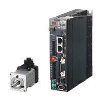
The 1S servo drive with motion safety functionality provides protection for the machine operators from fatal injuries and shorter machine downtimes. Integrating motion safety functions into the servo drive minimize costs, components and wiring complexity. This model supports motion safety but it is even further evolved based on the concept of the standard 1S series. With the highest-level of motion control performance and safety functionality, productivity can be further improved.

![R88M-1A[] / R88D-1SAN[]-ECT](/upload/product/omron/bot/omron_3776/picture.jpg)
R88M-1A[] / R88D-1SAN[]-ECT
產品特色
Safer environment and higher productivity
Simplifying Motion and Safety
![R88M-1A[] / R88D-1SAN[]-ECT 特長 1](/Images/3776_fe_118-302265.jpg)
Servo features
• Power range from 200 W to 3 kW
• 20 bit high resolution encoder
• 350% momentary maximum torque (200 V, 750 W max.)
• Battery-free absolute multi-turn encoder
• Safety over EtherCAT (FSoE)
![R88M-1A[] / R88D-1SAN[]-ECT 特長 3](/upload/product/omron/bot/omron_3776/b71967a4f297e28e3a57b87a4f7c4875.jpg)
High adaptability for machine safety
STO SS1 SS2 SOS SLS SLP SDI SBC (PLe SIL3) with FSoE
![R88M-1A[] / R88D-1SAN[]-ECT 特長 4](/Images/3776_fe_318-302267.jpg)
![R88M-1A[] / R88D-1SAN[]-ECT 特長 5](/upload/product/omron/bot/omron_3776/47b364046f688141b77078e9033b27bb.jpg)
Quick Installation : One Cable
• Power, encoder and brake in one pre-assembled cable with IP67 connector
• Pluggable connectors for easy pre-wiring and system maintenance
• Fast and secure screw-less push-in in all connectors
![R88M-1A[] / R88D-1SAN[]-ECT 特長 6](/upload/product/omron/bot/omron_3776/c90deaded12596ccacb99569a6c4ef7b.jpg)
Time Reduction: Integrated Programming and Testing
• Auto definition of I/F variables
• Motion safety function blocks
• Graphical GUI
• Integrated Data Trace
![R88M-1A[] / R88D-1SAN[]-ECT 特長 7](/upload/product/omron/bot/omron_3776/e8275aca43d776a51812ab0290f82974.jpg)
Motion Safety
Increase Machine Uptime
Minimize operation intervention time
![R88M-1A[] / R88D-1SAN[]-ECT 特長 9](/upload/product/omron/bot/omron_3776/5fd27572c5f67064e6a4626a5ce2f4d6.jpg)
ISSUE
• In a machine operation intervention such as removing a crashed product, the machine is stopped, so there is no production.
SOLUTION
• You can pickup the product safely with Safely-Limited Speed function. The production line is running at limited speed but it is not stopped.
• Machine restarts smoothly from speed limit to normal speed.
![R88M-1A[] / R88D-1SAN[]-ECT 特長 11](/upload/product/omron/bot/omron_3776/0179be95dacc5424f361f34c8c0e8982.jpg)
Reduce changeover time
![R88M-1A[] / R88D-1SAN[]-ECT 特長 12](/upload/product/omron/bot/omron_3776/afe566accdfc68ac3ce2ad119930ddf9.jpg)
ISSUE
• In a coil change, the machine operator has to set the material in each roll with inching or jog function. It makes the change over complex and time consuming.
SOLUTION
• Machine operator can set the material in the roll with Safely-Limited Speed and introduce the film smoothly with Safe Direction function. It helps the operator to reduce the change over time and complexity
![R88M-1A[] / R88D-1SAN[]-ECT 特長 14](/upload/product/omron/bot/omron_3776/ddb01583789d8e6084d187172961c45d.jpg)
Avoid machine stops
![R88M-1A[] / R88D-1SAN[]-ECT 特長 15](/upload/product/omron/bot/omron_3776/6cb9ea997c7c33d571fa6cca6c66c736.jpg)
ISSUE
• In a machine operation intervention, the stacker is stopped, so there is no production
SOLUTION
• When the operator is close, the stacker run slowly with Safely-Limited Speed without stopping.
• If the operator gets too close, then the Safe Brake Control function is activated to hold the stacker in a safer mode.
![R88M-1A[] / R88D-1SAN[]-ECT 特長 17](/upload/product/omron/bot/omron_3776/cc13c170ea19fa40e9f66d50ed2d7f4f.jpg)
Zero startup rejects
![R88M-1A[] / R88D-1SAN[]-ECT 特長 18](/upload/product/omron/bot/omron_3776/0de817d571ca15a8c0e69bf1b9796642.jpg)
ISSUE
• Disposal of product waste occurs. If the power to a motor is stopped following an emergency stop, film may be caught in the machine.
SOLUTION
• Even in the event of machine stoppage due to an emergency stop, disposal of product waste will not occur.
• Power is continuously supplied to a motor even during the emergency stop, therefore preventing film from getting caught in the machine.
![R88M-1A[] / R88D-1SAN[]-ECT 特長 20](/upload/product/omron/bot/omron_3776/5aa7906821ae22e4b370e47e90cceb13.jpg)
Sysmac Automation Platform
![R88M-1A[] / R88D-1SAN[]-ECT 特長 21](/upload/product/omron/bot/omron_3776/194a7ccfe4be2859120b52fb75599170.jpg)
Software
![R88M-1A[] / R88D-1SAN[]-ECT 特長 22](/upload/product/omron/bot/omron_3776/21db595e48d8f4d3e8b1254e18da20ef.jpg)
Sysmac Studio, the integrated software
• One single tool for logic sequence, motion, safety, robotics, vision and HMI
• Fully compliant with open standard IEC 61131-3
• PLCopen Function Blocks for Motion and Safety
• Supports Ladder, Structured Text and In-Line ST programming with a rich instruction set
• CAM editor for easy programming of complex motion profiles
• Database Connectivity Function Block library
Sysmac Library
• The Sysmac Library is a collection of software functional components that can be used in programs for the NJ/NX Machine Automation Controllers. Sample programs and HMI screen samples are also available.
Please download it from following URL and install to Sysmac Studio. https://www.ia.omron.com/sysmac_library/
Machine Controller
![R88M-1A[] / R88D-1SAN[]-ECT 特長 25](/upload/product/omron/bot/omron_3776/c5b91166a456c4ae86a9beb47a8fb533.jpg)
The NX-series Safety Network Controller connected with the NX1 Machine Controller enables the use of both EtherNet/IP + CIP Safety and EtherCAT + FSoE at the same time.
NJ/NX series
• Logic sequence, Motion, Safety, Robotics and Database connection functionality
• Scalable motion control: CPUs from 2 up to 256 axes
• IEC 61131-3 controller
• PLCopen Function Blocks for Motion Control and Safety
• Advanced motion with Robotics functionality
• Built-in EtherCAT and EtherNet/IP ports
Motion
![R88M-1A[] / R88D-1SAN[]-ECT 特長 27](/upload/product/omron/bot/omron_3776/327d3e01e78a518b5c61d3a87378cd42.jpg)
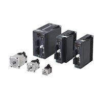
1S Motion Safety servo
• Servo drive for rotary motors
• Up to 3kW
• Battery-free absolute multi-turn encoder
• Advanced safety functions: STO/SS1/SS2/SOS/SLS/SLP/SDI/SBC
• Servo drive for rotary motors with one cable connection
![R88M-1A[] / R88D-1SAN[]-ECT 特長 29](/upload/product/omron/bot/omron_3776/0ee7d0ddafb3736f0414a6a83cfd75c2.jpg)
1S Servo System - General purpose servo
• Servo drive for rotary motors
• Up to 15kW
• Battery-free absolute multi-turn encoder
• Safety function: STO
![R88M-1A[] / R88D-1SAN[]-ECT 特長 31](/upload/product/omron/bot/omron_3776/cb76b8ade7052cc03f08671456c37718.jpg)
G5 Servo System
• Servo drive for rotary or linear motors
• Rotary motor: Up to 15 kW
• Iron-core and Ironless linear motor models: Up to 2100 N peak force
• Safety function: STO (Hardwired Safe Torque Off only)
• Full closed loop control
Sysmac is a trademark or registered trademark of OMRON Corporation in Japan and other countries for OMRON factory automation products. Windows, and SQL Server are either registered trademarks or trademarks of Microsoft Corporation in the United Status and/or other countries. EtherCAT® and Safery over EtherCAT® are registered trademarks and patented technologies, licensed by Beckhoff Automation GmbH, Germany. EtherNet/IP™ and CIP Safety™ are trademarks of ODVA. Other company names and product names in this document are the trademarks or registered trademarks of their respective companies.
The product photographs and figures that are used in this catalog may vary somewhat from the actual products. Microsoft product screen shot(s) reprinted with permission from Microsoft Corporation. Some images are used under license from Shutterstock.com.
Interpreting Model Numbers
![R88M-1A[] / R88D-1SAN[]-ECT 種類 1](/upload/product/omron/bot/omron_3776/c6faff2a9c1427f743a18271012fecf9.gif)
![R88M-1A[] / R88D-1SAN[]-ECT 種類 2](/upload/product/omron/bot/omron_3776/5f6270b16c49db6dec2ceb9540548284.gif)
Table of AC Servomotor Variations
![R88M-1A[] / R88D-1SAN[]-ECT 種類 3](/upload/product/omron/bot/omron_3776/1b4edcd02ca79ded13936f71e15892f5.gif)
Ordering Information
AC Servo Drives with Built-in EtherCAT Communications and Safety Functionality
| Power supply voltage | Rated output | Model |
|---|---|---|
| Single-phase/3-phase 200 VAC |
200 W | R88D-1SAN02H-ECT |
| 400 W | R88D-1SAN04H-ECT | |
| 750 W | R88D-1SAN08H-ECT | |
| 1.5 kW | R88D-1SAN15H-ECT | |
| 3-phase 200 VAC | 1 kW | R88D-1SAN10H-ECT |
| 2 kW | R88D-1SAN20H-ECT | |
| 3 kW | R88D-1SAN30H-ECT | |
| 3-phase 400 VAC | 1 kW | R88D-1SAN10F-ECT |
| 1.5 kW | R88D-1SAN15F-ECT | |
| 2 kW | R88D-1SAN20F-ECT | |
| 3 kW | R88D-1SAN30F-ECT |
AC Servomotors with Safety Functionality
3,000-r/min Servomotors
| Specifications | Model | |||
|---|---|---|---|---|
| Without oil seal | ||||
| Straight shaft | With key and tap | |||
| Without brake | 200 VAC | 200 W | R88M-1AM20030T | R88M-1AM20030T-S2 |
| 400 W | R88M-1AM40030T | R88M-1AM40030T-S2 | ||
| 750 W | R88M-1AM75030T | R88M-1AM75030T-S2 | ||
| 1 kW | R88M-1AL1K030T | R88M-1AL1K030T-S2 | ||
| 1.5 kW | R88M-1AL1K530T | R88M-1AL1K530T-S2 | ||
| 2 kW | R88M-1AL2K030T | R88M-1AL2K030T-S2 | ||
| 2.6 kW | R88M-1AL2K630T | R88M-1AL2K630T-S2 | ||
| 400 VAC | 750 W | R88M-1AL75030C | R88M-1AL75030C-S2 | |
| 1 kW | R88M-1AL1K030C | R88M-1AL1K030C-S2 | ||
| 1.5 kW | R88M-1AL1K530C | R88M-1AL1K530C-S2 | ||
| 2 kW | R88M-1AL2K030C | R88M-1AL2K030C-S2 | ||
| 3 kW | R88M-1AL3K030C | R88M-1AL3K030C-S2 | ||
| With brake | 200 VAC | 200 W | R88M-1AM20030T-B | R88M-1AM20030T-BS2 |
| 400 W | R88M-1AM40030T-B | R88M-1AM40030T-BS2 | ||
| 750 W | R88M-1AM75030T-B | R88M-1AM75030T-BS2 | ||
| 1 kW | R88M-1AL1K030T-B | R88M-1AL1K030T-BS2 | ||
| 1.5 kW | R88M-1AL1K530T-B | R88M-1AL1K530T-BS2 | ||
| 2 kW | R88M-1AL2K030T-B | R88M-1AL2K030T-BS2 | ||
| 2.6 kW | R88M-1AL2K630T-B | R88M-1AL2K630T-BS2 | ||
| 400 VAC | 750 W | R88M-1AL75030C-B | R88M-1AL75030C-BS2 | |
| 1 kW | R88M-1AL1K030C-B | R88M-1AL1K030C-BS2 | ||
| 1.5 kW | R88M-1AL1K530C-B | R88M-1AL1K530C-BS2 | ||
| 2 kW | R88M-1AL2K030C-B | R88M-1AL2K030C-BS2 | ||
| 3 kW | R88M-1AL3K030C-B | R88M-1AL3K030C-BS2 | ||
| Specifications | Model | |||
|---|---|---|---|---|
| With oil seal | ||||
| Straight shaft | With key and tap | |||
| Without brake | 200 VAC | 200 W | R88M-1AM20030T-O | R88M-1AM20030T-OS2 |
| 400 W | R88M-1AM40030T-O | R88M-1AM40030T-OS2 | ||
| 750 W | R88M-1AM75030T-O | R88M-1AM75030T-OS2 | ||
| 1 kW | R88M-1AL1K030T-O | R88M-1AL1K030T-OS2 | ||
| 1.5 kW | R88M-1AL1K530T-O | R88M-1AL1K530T-OS2 | ||
| 2 kW | R88M-1AL2K030T-O | R88M-1AL2K030T-OS2 | ||
| 2.6 kW | R88M-1AL2K630T-O | R88M-1AL2K630T-OS2 | ||
| 400 VAC | 750 W | R88M-1AL75030C-O | R88M-1AL75030C-OS2 | |
| 1 kW | R88M-1AL1K030C-O | R88M-1AL1K030C-OS2 | ||
| 1.5 kW | R88M-1AL1K530C-O | R88M-1AL1K530C-OS2 | ||
| 2 kW | R88M-1AL2K030C-O | R88M-1AL2K030C-OS2 | ||
| 3 kW | R88M-1AL3K030C-O | R88M-1AL3K030C-OS2 | ||
| With brake | 200 VAC | 200 W | R88M-1AM20030T-BO | R88M-1AM20030T-BOS2 |
| 400 W | R88M-1AM40030T-BO | R88M-1AM40030T-BOS2 | ||
| 750 W | R88M-1AM75030T-BO | R88M-1AM75030T-BOS2 | ||
| 1 kW | R88M-1AL1K030T-BO | R88M-1AL1K030T-BOS2 | ||
| 1.5 kW | R88M-1AL1K530T-BO | R88M-1AL1K530T-BOS2 | ||
| 2 kW | R88M-1AL2K030T-BO | R88M-1AL2K030T-BOS2 | ||
| 2.6 kW | R88M-1AL2K630T-BO | R88M-1AL2K630T-BOS2 | ||
| 400 VAC | 750 W | R88M-1AL75030C-BO | R88M-1AL75030C-BOS2 | |
| 1 kW | R88M-1AL1K030C-BO | R88M-1AL1K030C-BOS2 | ||
| 1.5 kW | R88M-1AL1K530C-BO | R88M-1AL1K530C-BOS2 | ||
| 2 kW | R88M-1AL2K030C-BO | R88M-1AL2K030C-BOS2 | ||
| 3 kW | R88M-1AL3K030C-BO | R88M-1AL3K030C-BOS2 | ||
1,500-r/min Servomotors
| Specifications | Model | |||
|---|---|---|---|---|
| Without oil seal | ||||
| Straight shaft | With key and tap | |||
| Without brake | 200 VAC | 1.5 kW | R88M-1AM1K515T | R88M-1AM1K515T-S2 |
| 2.7 kW | R88M-1AM2K715T | R88M-1AM2K715T-S2 | ||
| 400 VAC | 1.5 kW | R88M-1AM1K515C | R88M-1AM1K515C-S2 | |
| 3 kW | R88M-1AM3K015C | R88M-1AM3K015C-S2 | ||
| With brake | 200 VAC | 1.5 kW | R88M-1AM1K515T-B | R88M-1AM1K515T-BS2 |
| 2.7 kW | R88M-1AM2K715T-B | R88M-1AM2K715T-BS2 | ||
| 400 VAC | 1.5 kW | R88M-1AM1K515C-B | R88M-1AM1K515C-BS2 | |
| 3 kW | R88M-1AM3K015C-B | R88M-1AM3K015C-BS2 | ||
| Specifications | Model | |||
|---|---|---|---|---|
| With oil seal | ||||
| Straight shaft | With key and tap | |||
| Without brake | 200 VAC | 1.5 kW | R88M-1AM1K515T-O | R88M-1AM1K515T-OS2 |
| 2.7 kW | R88M-1AM2K715T-O | R88M-1AM2K715T-OS2 | ||
| 400 VAC | 1.5 kW | R88M-1AM1K515C-O | R88M-1AM1K515C-OS2 | |
| 3 kW | R88M-1AM3K015C-O | R88M-1AM3K015C-OS2 | ||
| With brake | 200 VAC | 1.5 kW | R88M-1AM1K515T-BO | R88M-1AM1K515T-BOS2 |
| 2.7 kW | R88M-1AM2K715T-BO | R88M-1AM2K715T-BOS2 | ||
| 400 VAC | 1.5 kW | R88M-1AM1K515C-BO | R88M-1AM1K515C-BOS2 | |
| 3 kW | R88M-1AM3K015C-BO | R88M-1AM3K015C-BOS2 | ||
Decelerator (Backlash: 3 Arcminutes Max.)
For 3,000-r/min Servomotors
| Servomotor rated output | Reduction ratio | Model (Straight shaft) * |
|---|---|---|
| 200 W | 1/5 | R88G-HPG14A05200B[] |
| 1/11 | R88G-HPG14A11200B[] | |
| 1/21 | R88G-HPG20A21200B[] | |
| 1/33 | R88G-HPG20A33200B[] | |
| 1/45 | R88G-HPG20A45200B[] | |
| 400 W | 1/5 | R88G-HPG14A05400B[] |
| 1/11 | R88G-HPG20A11400B[] | |
| 1/21 | R88G-HPG20A21400B[] | |
| 1/33 | R88G-HPG32A33400B[] | |
| 1/45 | R88G-HPG32A45400B[] | |
| 750 W (200 V) |
1/5 | R88G-HPG20A05750B[] |
| 1/11 | R88G-HPG20A11750B[] | |
| 1/21 | R88G-HPG32A21750B[] | |
| 1/33 | R88G-HPG32A33750B[] | |
| 1/45 | R88G-HPG32A45750B[] | |
| 750 W (400 V) |
1/5 | R88G-HPG32A052K0B[] |
| 1/11 | R88G-HPG32A112K0B[] | |
| 1/21 | R88G-HPG32A211K5B[] | |
| 1/33 | R88G-HPG32A33600SB[] | |
| 1 kW | 1/5 | R88G-HPG32A052K0B[] |
| 1/11 | R88G-HPG32A112K0B[] | |
| 1/21 | R88G-HPG32A211K5B[] | |
| 1.5 kW | 1/5 | R88G-HPG32A052K0B[] |
| 1/11 | R88G-HPG32A112K0B[] | |
| 1/21 | R88G-HPG32A211K5B[] | |
| 2 kW | 1/5 | R88G-HPG32A052K0B[] |
| 1/11 | R88G-HPG32A112K0B[] | |
| 2.6 kW (200 V) 3 kW (400 V) |
1/5 | R88G-HPG32A053K0B[] |
* The standard shaft type is a straight shaft. A model with a key and tap is indicated with “J” at [] of the Decelerator model
number. e.g. R88G-HPG11B05100BJ
number. e.g. R88G-HPG11B05100BJ
For 1,500-r/min Servomotors
| Servomotor rated output | Reduction ratio | Model (Straight shaft) * |
|---|---|---|
| 1.5 kW | 1/5 | R88G-HPG32A053K0B[] |
| 1/11 | R88G-HPG32A112K0SB[] | |
| 1/21 | R88G-HPG50A21900TB[] | |
| 1/33 | R88G-HPG50A33900TB[] | |
| 2.7 kW (200 V) 3 kW (400 V) |
1/5 | R88G-HPG50A055K0SB[] |
| 1/11 | R88G-HPG50A115K0SB[] | |
| 1/20 | R88G-HPG65A205K0SB[] | |
| 1/25 | R88G-HPG65A255K0SB[] |
* The standard shaft type is a straight shaft. A model with a key and tap is indicated with “J” at [] of the Decelerator model
number. e.g. R88G-HPG11B05100BJ
number. e.g. R88G-HPG11B05100BJ
Decelerator (Backlash: 15 Arcminutes Max.)
For 3,000-r/min Servomotors
| Servomotor rated output | Reduction ratio | Model |
|---|---|---|
| 200 W | 1/5 | R88G-VRXF05B200CJ |
| 1/9 | R88G-VRXF09C200CJ | |
| 1/15 | R88G-VRXF15C200CJ | |
| 1/25 | R88G-VRXF25C200CJ | |
| 400 W | 1/5 | R88G-VRXF05C400CJ |
| 1/9 | R88G-VRXF09C400CJ | |
| 1/15 | R88G-VRXF15C400CJ | |
| 1/25 | R88G-VRXF25C400CJ | |
| 750 W (200 V) |
1/5 | R88G-VRXF05C750CJ |
| 1/9 | R88G-VRXF09D750CJ | |
| 1/15 | R88G-VRXF15D750CJ | |
| 1/25 | R88G-VRXF25D750CJ |
Cables and Peripheral Devices
Integrated Cable (Flexible Cable)
| Applicable Servomotor | Without brake wire | With brake wire | ||
|---|---|---|---|---|
| Model | Model | |||
| 200 V | 3,000-r/min Servomotors of 200 W, 400 W, 750 W | 3 m | R88A-CX1A003SF | R88A-CX1A003BF |
| 5 m | R88A-CX1A005SF | R88A-CX1A005BF | ||
| 10 m | R88A-CX1A010SF | R88A-CX1A010BF | ||
| 15 m | R88A-CX1A015SF | R88A-CX1A015BF | ||
| 20 m | R88A-CX1A020SF | R88A-CX1A020BF | ||
| 200 V | 3,000-r/min Servomotors of 1 kW | 3 m | R88A-CX1B003SF | R88A-CX1B003BF |
| 5 m | R88A-CX1B005SF | R88A-CX1B005BF | ||
| 10 m | R88A-CX1B010SF | R88A-CX1B010BF | ||
| 15 m | R88A-CX1B015SF | R88A-CX1B015BF | ||
| 20 m | R88A-CX1B020SF | R88A-CX1B020BF | ||
| 200 V 400 V |
200 V 3,000-r/min Servomotors of 1.5 kW 1,500-r/min Servomotors of 1.5 kW 400 V 3,000-r/min Servomotors of 750 W, 1 kW, 1.5 kW, 2 kW, 3 kW 1,500-r/min Servomotors of 1.5 kW, 3 kW |
3 m | R88A-CX1C003SF | R88A-CX1C003BF |
| 5 m | R88A-CX1C005SF | R88A-CX1C005BF | ||
| 10 m | R88A-CX1C010SF | R88A-CX1C010BF | ||
| 15 m | R88A-CX1C015SF | R88A-CX1C015BF | ||
| 20 m | R88A-CX1C020SF | R88A-CX1C020BF | ||
| 200 V | 3,000-r/min Servomotors of 2 kW, 2.6 kW 1,500-r/min Servomotors of 2.7 kW |
3 m | R88A-CX1D003SF | R88A-CX1D003BF |
| 5 m | R88A-CX1D005SF | R88A-CX1D005BF | ||
| 10 m | R88A-CX1D010SF | R88A-CX1D010BF | ||
| 15 m | R88A-CX1D015SF | R88A-CX1D015BF | ||
| 20 m | R88A-CX1D020SF | R88A-CX1D020BF | ||
Extension Power Cable (Flexible Cable)
Use the cables listed below to extend the integrated cable either with or without brake wire.
Also, use R88A-CX1BE[][]BF when you use an extension cable for R88A-CX1C[][][][]F.
| Applicable Servomotor | Model | ||
|---|---|---|---|
| 200 V | 3,000-r/min Servomotors of 200 W, 400 W, 750 W | 10 m | R88A-CX1AE10BF |
| 20 m | R88A-CX1AE20BF | ||
| 200 V 400 V |
200 V 3,000-r/min Servomotors of 1 kW, 1.5 kW 1,500-r/min Servomotors of 1.5 kW 400 V 3,000-r/min Servomotors of 750 W, 1 kW, 1.5 kW, 2 kW, 3 kW 1,500r/min Servomotors of 1.5 kW, 3 kW |
10 m | R88A-CX1BE10BF |
| 20 m | R88A-CX1BE20BF | ||
| 200 V | 3,000-r/min Servomotors of 2 kW, 2.6 kW 1,500-r/min Servomotors of 2.7 kW |
10 m | R88A-CX1DE10BF |
| 20 m | R88A-CX1DE20BF | ||
Recommended EtherCAT Communications Cable
Use a straight STP (shielded twisted-pair) cable of category 5 or higher with double shielding (braiding and aluminum foil tape) for EtherCAT.
Cabel with Connectors
| Item | Appearance | Recommended manufacturer |
Cable length [m] |
Model |
|---|---|---|---|---|
| Cable with Connectors on Both Ends (RJ45/RJ45) Standard RJ45 plugs type *1 Wire gauge and number of pairs: AWG26, 4-pair cable Cable sheath material: LSZH *2 Cable color: Yellow *3 |
 |
OMRON | 0.3 | XS6W-6LSZH8SS30CM-Y |
| 0.5 | XS6W-6LSZH8SS50CM-Y | |||
| 1 | XS6W-6LSZH8SS100CM-Y | |||
| 2 | XS6W-6LSZH8SS200CM-Y | |||
| 3 | XS6W-6LSZH8SS300CM-Y | |||
| 5 | XS6W-6LSZH8SS500CM-Y | |||
| Cable with Connectors on Both Ends (RJ45/RJ45) Rugged RJ45 plugs type *1 Wire gauge and number of pairs: AWG22, 2-pair cable Cable color: Light blue |
 |
OMRON | 0.3 | XS5W-T421-AMD-K |
| 0.5 | XS5W-T421-BMD-K | |||
| 1 | XS5W-T421-CMD-K | |||
| 2 | XS5W-T421-DMD-K | |||
| 5 | XS5W-T421-GMD-K | |||
| 10 | XS5W-T421-JMD-K | |||
| Cable with Connectors on Both Ends (M12 Straight/M12 Straight) Shield Strengthening Connector cable *4 M12/Smartclick Connectors Wire Gauge and Number of Pairs: AWG22, 2-pair cable Cable color: Black |
 |
OMRON | 0.5 | XS5W-T421-BM2-SS |
| 1 | XS5W-T421-CM2-SS | |||
| 2 | XS5W-T421-DM2-SS | |||
| 3 | XS5W-T421-EM2-SS | |||
| 5 | XS5W-T421-GM2-SS | |||
| 10 | XS5W-T421-JM2-SS | |||
| Cable with Connectors on Both Ends (M12 Straight/RJ45) Shield Strengthening Connector cable *4 M12/Smartclick Connectors Rugged RJ45 plugs type Wire Gauge and Number of Pairs: AWG22, 2-pair cable Cable color: Black |
 |
OMRON | 0.5 | XS5W-T421-BMC-SS |
| 1 | XS5W-T421-CMC-SS | |||
| 2 | XS5W-T421-DMC-SS | |||
| 3 | XS5W-T421-EMC-SS | |||
| 5 | XS5W-T421-GMC-SS | |||
| 10 | XS5W-T421-JMC-SS |
*1. Standard type cables length 0.2, 0.3, 0.5, 1, 1.5, 2, 3, 5, 7.5, 10, 15 and 20 m are available.
Rugged type cables length 0.3, 0.5, 1, 2, 3, 5, 10 and 15 m are available.
For details, refer to Cat.No.G019.
*2. The lineup features Low Smoke Zero Halogen cables for in-cabinet use and PUR cables for out-of-cabinet use. Although
the LSZH cable is single shielded, its communications and noise characteristics meet the standards.
*3. Cables colors are available in blue, yellow, or Green.
*4. For details, contact your OMRON representative.
Cables/Connectors
Wire Gauge and Number of Pairs: AWG24, 4-pair Cable
| Item | Appearance | Recommended manufacturer | Model |
|---|---|---|---|
| Cables | --- | Hitachi Metals, Ltd. | NETSTAR-C5E SAB 0.5 × 4P CP * |
| --- | Kuramo Electric Co. | KETH-SB * | |
| --- | SWCC Showa Cable Systems Co. | FAE-5004 * | |
| RJ45 Connectors | --- | Panduit Corporation | MPS588-C * |
* We recommend you to use above cable and connector together.
Wire Gauge and Number of Pairs: AWG22, 2-pair Cable
| Item | Appearance | Recommended manufacturer | Model |
|---|---|---|---|
| Cables | --- | Kuramo Electric Co. | KETH-PSB-OMR * |
| --- | JMACS Japan Co., Ltd. | PNET/B * | |
| RJ45 Assembly Connector |  |
OMRON | XS6G-T421-1 * |
* We recommend you to use above cable and connector together.
Peripheral Connector
Servo Drive Side Connectors
One of each of servo drive side connectors (except the encoder connector) are included with the R88D-1SN[]-ECT AC Servo Drive.
All connecters are also available separately for maintenance.
| Name and applications | Model |
|---|---|
| Main circuit connector (CNA) *1 For R88D-1SAN02H-ECT/ -1SAN04H-ECT/ -1SAN08H-ECT/ -1SAN10H-ECT |
R88A-CN102P *4 |
| Main circuit connector A (CNA) *2 For R88D-1SAN15H-ECT/ -1SAN20H-ECT/ -1SAN30H-ECT/ -1SAN10F-ECT/-1SAN15F-ECT/ -1SAN20F-ECT/ -1SAN30F-ECT |
R88A-CN103P *4 |
| Main circuit connector B (CNB) *2 For R88D-1SAN15H-ECT/ -1SAN20H-ECT/ -1SAN30H-ECT/ -1SAN10F-ECT/-1SAN15F-ECT/ -1SAN20F-ECT/ -1SAN30F-ECT |
R88A-CN104P *4 |
| Motor connector (CNC) For R88D-1SAN02H-ECT/ -1SAN04H-ECT/ -1SAN08H-ECT/ -1SAN10H-ECT |
R88A-CN101A *4 |
| Motor connector (CNC) For R88D-1SAN15H-ECT/ -1SAN20H-ECT/ -1SAN30H-ECT/ -1SAN10F-ECT/-1SAN15F-ECT/ -1SAN20F-ECT/ -1SAN30F-ECT |
R88A-CN102A *4 |
| Control power supply connector (CND) For R88D-1SAN15H-ECT/ -1SAN20H-ECT/ -1SAN30H-ECT/ -1SAN10F-ECT/-1SAN15F-ECT/ -1SAN20F-ECT/ -1SAN30F-ECT |
R88A-CN101P *4 |
| Control I/O connector (CN1) | R88A-CN102C |
| Encoder connector (CN2) | R88A-CN101R |
| Brake interlock connector (CN12) | R88A-CN101B |
| Safety signal connector (CN14) *3 | R88A-CN101S |
| Safe brake control connector (CN15) | R88A-CN102S |
*1. Two short-circuit wires are connected to the connector.
*2. One short-circuit wire is connected to the connector.
*3. Four short-circuit wires are connected to the connector. One pin to prevent improper wiring are included.
*4. One opener is included
Shield Clamp Bracket
A shield clamp is used to fix the integrated cable and to connect the shield of the integrated cable to FG of the servo drive. The shield clamp consists of the shield clamp bracket and shield clamp plate.
| Name | Applicable Servo Drive and Integrated Cables | Model | |
|---|---|---|---|
| Shield Clamp Bracket S |
R88D-1SAN02H-ECT R88D-1SAN04H-ECT R88D-1SAN08H-ECT |
R88A-CX1A[][][][]F | R88A-SC10CX |
| R88D-1SAN10H-ECT | R88A-CX1B[][][][]F | ||
| R88D-1SAN15H-ECT R88D-1SAN10F-ECT R88D-1SAN15F-ECT R88D-1SAN20F-ECT R88D-1SAN30F-ECT |
R88A-CX1C[][][][]F | ||
| R88D-1SAN20H-ECT R88D-1SAN30H-ECT |
R88A-CX1D[][][][]F | ||
Note: An applicable Integrated cable comes with a shield clamp bracket.
An extension cable does not come with a shield clamp bracket.
An extension cable does not come with a shield clamp bracket.
External Regeneration Resistors
| Applicable Servo Drive | Specifications | Model |
|---|---|---|
| R88D-1SAN02H-ECT | Regeneration process capacity: 24 W, 25 Ω | R88A-RR12025 |
| R88D-1SAN30H-ECT | Regeneration process capacity: 60 W, 8 Ω | R88A-RR30008 |
| R88D-1SAN20H-ECT | Regeneration process capacity: 60 W, 10 Ω | R88A-RR30010 |
| R88D-1SAN15H-ECT | Regeneration process capacity: 60 W, 14 Ω | R88A-RR30014 |
| R88D-1SAN08H-ECT/-1SAN10H-ECT/ -1SAN20F-ECT * |
Regeneration process capacity: 60 W, 20 Ω | R88A-RR30020 |
| R88D-1SAN02H-ECT/-1SAN04H-ECT | Regeneration process capacity: 60 W, 25 Ω | R88A-RR30025 |
| R88D-1SAN30F-ECT | Regeneration process capacity: 60 W, 32 Ω | R88A-RR30032 |
| R88D-1SAN10F-ECT * | Regeneration process capacity: 60 W, 33 Ω | R88A-RR30033 |
| R88D-1SAN15F-ECT | Regeneration process capacity: 60 W, 54 Ω | R88A-RR30054 |
* Use two series-connected External Regeneration Resistors for this model.
External Regeneration Resistance Unit
| Applicable Servo Drive | Specifications | Model |
|---|---|---|
| R88D-1SAN30H-ECT | Regeneration process capacity: 640 W, 8 Ω | R88A-RR1K608 |
| R88D-1SAN20H-ECT | Regeneration process capacity: 640 W, 10 Ω | R88A-RR1K610 |
| R88D-1SAN15H-ECT | Regeneration process capacity: 640 W, 14 Ω | R88A-RR1K614 |
| R88D-1SAN08H-ECT/-1SAN10H-ECT/ -1SAN20F-ECT * |
Regeneration process capacity: 640 W, 20 Ω | R88A-RR1K620 |
| R88D-1SAN30F-ECT | Regeneration process capacity: 640 W, 32 Ω | R88A-RR1K632 |
| R88D-1SAN20F-ECT | Regeneration process capacity: 640 W, 40 Ω | R88A-RR1K640 |
| R88D-1SAN15F-ECT | Regeneration process capacity: 640 W, 54 Ω | R88A-RR1K654 |
| R88D-1SAN10F-ECT | Regeneration process capacity: 640 W, 66 Ω | R88A-RR1K666 |
* Use two series-connected External Regeneration Resistors for this model.
DC Reactor
| Applicable Servo Drive | Model |
|---|---|
| R88D-1SAN02H-ECT | R88A-PD2002 |
| R88D-1SAN04H-ECT | R88A-PD2004 |
| R88D-1SAN08H-ECT | R88A-PD2007 |
| R88D-1SAN10H-ECT/ -1SAN15H-ECT | R88A-PD2015 |
| R88D-1SAN20H-ECT | R88A-PD2022 |
| R88D-1SAN30H-ECT | R88A-PD2037 |
| R88D-1SAN10F-ECT/ -1SAN15F-ECT | R88A-PD4015 |
| R88D-1SAN20F-ECT | R88A-PD4022 |
| R88D-1SAN30F-ECT | R88A-PD4037 |
Software
Automation Software Sysmac Studio
Please purchase a DVD and required number of licenses the first time you purchase the Sysmac Studio. DVDs and licenses are available individually. Each model of licenses does not include any DVD.
| Product name |
Specifications | Model | ||
|---|---|---|---|---|
| Number of licenses |
Media | |||
| Sysmac Studio Standard Edition Ver.1.[][] *1 |
The Sysmac Studio is the software that provides an integrated environment for setting, programming, debugging and maintenance of machine automation controllers including the NJ/NX-series CPU Units, NY-series Industrial PC, EtherCat Slave, and the HMI. Sysmac Studio runs on the following OS. Windows 7 (32-bit/64-bit version)/Windows 8 (32-bit/64-bit version)/Windows 8.1 (32-bit/64-bit version)/Windows 10 (32-bit/64-bit version) *2 The Sysmac Studio Standard Edition DVD includes Support Software to set up EtherNet/IP Units, DeviceNet slaves, Serial Communications Units, and Support Software for creating screens on HMIs (CX-Designer). For details, refer to your OMRON website. |
--- (Media only) |
Sysmac Studio (32 bit) DVD |
SYSMAC-SE200D |
| --- (Media only) |
Sysmac Studio (64 bit) DVD |
SYSMAC-SE200D-64 | ||
| 1 license *3 |
--- | SYSMAC-SE201L | ||
| Sysmac Studio Drive Edition Ver.1.[][] |
Sysmac Studio Drive Edition is a limited license that provides selected functions required for 1S/G5 series Servo settings. This product is a license only. You need the Sysmac Studio Standard Edition DVD media to install it. With Drive Edition, you can use only the setup functions for 1S, G5-series Servo System |
1 license | --- | SYSMAC-DE001L |
*1 The 1S-series Safety Servo Drive unit version 1.0 or later is supported by Sysmac Studio version 1.44.1 or higher.
*2 Model "SYSMAC-SE200D-64" runs on Windows 10 (64 bit).
*3 Multi licenses are available for the Sysmac Studio (3, 10, 30, or 50 licenses).
Collections of software functional components
Sysmac Library
Sysmac Library is POU Libraries (Function Block and Function) provided for NJ/NX-series Controller.
Please download it from following URL and install to Sysmac Studio.
https://www.ia.omron.com/sysmac_library/
| Product | Features | Model |
|---|---|---|
| EtherCAT 1S Series Library |
The EtherCAT 1S Series Library is used to initialize the absolute encoder, back up and restore the parameters for an OMRON 1S-series Servo Drive with built-in EtherCAT communications. You can use this library to reduce manpower of programming when implementing the processing for a Servo Drive. |
SYSMAC-XR011 |
AC Servo Drives with Built-in EtherCAT Communications [1S-series with Safety Functionality]
Specifications
General Specifications
| Item | Specifications | ||
|---|---|---|---|
| Operating ambient temperature and humidity | 0 to 55°C, 90% max. (with no condensation) | ||
| Storage ambient temperature and humidity | -20 to 65°C, 90% max. (with no condensation) | ||
| Operating and storage atmosphere | No corrosive gases | ||
| Operating altitude | 1,000 m max. | ||
| Vibration resistance | 10 to 60 Hz and at an acceleration of 5.88 m/s2 or less (Not to be run continuously at the resonance frequency) |
||
| Insulation resistance | Between power supply terminals/power terminals and PE terminals: 0.5 MΩ min. (at 500 VDC) |
||
| Dielectric strength | Between power supply terminals/power terminals and PE terminals: 1,500 VAC for 1 min (at 50/60 Hz) |
||
| Protective structure | IP20 (Built into IP54 panel) | ||
| International standard |
EU Directives | EMC Directive | EN 61800-3 second environment, C3 category (EN 61000-6-7; Functional Safety) |
| Low Voltage Directive | EN61800-5-1 | ||
| Machinery Directive | EN ISO 13849-1, EN61508, EN62061, EN61800-5-2 | ||
| UL standards | UL 61800-5-1 | ||
| CSA standards | CSA C22.2 No. 274 | ||
| Korean Radio Regulations (KC) | Compliant | ||
| Australian EMC Labeling Requirements (RCM) |
Compliant | ||
| EAC requirements | Compliant | ||
| SEMI standards | Can conform to the standard for momentary power interruptions (for no-load operation). |
||
| Ship standards (NK/LR) | Not compliant | ||
Note: 1. The above items reflect individual evaluation testing. The results may differ under compound conditions.
2. Disconnect all connections to the Servo Drive before attempting a megger test (insulation resistance measurement)
on a Servo Drive.
Not doing so may result in the Servo Drive failure.
Do not perform a dielectric strength test on the Servo Drive. Internal elements may be damaged.
2. Disconnect all connections to the Servo Drive before attempting a megger test (insulation resistance measurement)
on a Servo Drive.
Not doing so may result in the Servo Drive failure.
Do not perform a dielectric strength test on the Servo Drive. Internal elements may be damaged.
The detail of Machinery Directive is as follows:
The STO function via safety input signals: EN ISO13849-1 (Cat3 PLe), EN61508, EN62061, EN61800-5-2 (SIL3)
The safety function via EtherCAT communications: EN ISO 13849-1 (STO/SS1/SBC: Cat.3 PLe, SS2/SLS/SDI/SOS/SLP: Cat.3 PLe), EN61508, EN62061, EN61800-5-2
Characteristics
200-VAC Input Models
| Servo Drive model (R88D-) | 1SAN02H-ECT | 1SAN04H-ECT | 1SAN08H-ECT | ||
|---|---|---|---|---|---|
| Item | 200 W | 400 W | 750 W | ||
| Input | Main circuit | Power supply voltage | Single-phase and 3-phase 200 to 240 VAC (170 to 252 V) *1 | ||
| Frequency | 50/60 Hz (47.5 to 63 Hz) *1 | ||||
| Control circuit | Power supply voltage | 24 VDC (21.6 to 26.4 V) | |||
| Current consumption *2 | 700 mA | ||||
| Rated current [A (rms)] (Main circuit power supply voltage: 240 VAC) |
Singlephase | 2.7 | 4.6 | 7.3 | |
| 3-phase | 1.5 | 2.7 | 4.0 | ||
| Output | Rated current [A (rms)] | 1.5 | 2.5 | 4.6 | |
| Maximum current [A (rms)] | 5.6 | 9.1 | 16.9 | ||
| Heating value [W] | Main circuit | 17.0 | 25.0 | 42.0 | |
| Control circuit | 11.9 | 11.9 | 14.5 | ||
| Applicable Servomotor rated output [W] | 200 | 400 | 750 | ||
| 3,000-r/min Servomotor (R88M-) |
Batteryless 20-bit ABS | 1AM20030T | 1AM40030T | 1AM75030T | |
| Hold time at momentary power interruption (Main circuit power supply voltage: 200 VAC) |
10 ms (Load condition: rated output) *4 | ||||
| SCCR [A (rms)] | 5000 | ||||
| Weight [kg] | 2.6 | 2.6 | 2.6 | ||
| Servo Drive model (R88D-) | 1SAN10H-ECT | 1SAN15H-ECT | 1SAN20H-ECT | 1SAN30H-ECT | ||
|---|---|---|---|---|---|---|
| Item | 1 kW | 1.5 kW | 2 kW | 3 kW | ||
| Input | Main circuit | Power supply voltage |
3-phase 200 to 240 VAC (170 to 252 V) *1 |
Single-phase and 3-phase 200 to 240 VAC (170 to 252 V) *1 |
3-phase 200 to 240 VAC (170 to 252 V) *1 |
|
| Frequency | 50/60 Hz (47.5 to 63 Hz) *1 | |||||
| Control circuit | Power supply voltage |
24 VDC (21.6 to 26.4 V) | ||||
| Current consumption *2 |
700 mA | 1000 mA | ||||
| Rated current [A (rms)] (Main circuit power supply voltage: 240 VAC) |
Singlephase | --- | 15.7 | --- | --- | |
| 3-phase | 5.8 | 9.0 | 13.0 | 15.9 | ||
| Output | Rated current [A (rms)] | 7.7 | 9.7 | 16.2 | 22.3 | |
| Maximum current [A (rms)] | 16.9 | 28.4 | 41.0 | 54.7 | ||
| Heating value [W] | Main circuit *3 | 49.0 | 88.0 | 140.0 | 150.0 | |
| Control circuit | 14.5 | 22.4 | 22.4 | 22.4 | ||
| Applicable Servomotor rated output [W] | 1,000 | 1,500 | 2,000 | 3,000 | ||
| 3,000-r/min Servomotor (R88M-) |
Batteryless 20-bit ABS |
1AL1K030T | 1AL1K530T | 1AL2K030T | 1AL2K630T | |
| 1,500-r/min Servomotor (R88M-) |
Batteryless 20-bit ABS |
--- | 1AM1K515T | --- | 1AM2K715T | |
| Hold time at momentary power interruption (Main circuit power supply voltage: 200 VAC) |
10 ms (Load condition: rated output) *4 | |||||
| SCCR [A (rms)] | 5000 | |||||
| Weight [kg] | 2.6 | 4.2 | 4.2 | 4.2 | ||
*1. The values outside parentheses indicate the rated value, and the values inside parentheses indicate the range of
acceptable variation.
*2. Select a DC power supply in consideration of the current values that are specified in the current consumption. The rated
current value that is printed on the product nameplate is a condition to apply the 1S-series product for the UL/Low
Voltage Directive.
Therefore, you do not need to consider it when you select a DC power supply for each model.
*3. This is the maximum heating value in applicable Servomotors.
Refer to Relationship between Servo Drive, Servomotors and the Main Circuit Heating Value on below for the heating
value of each applicable Servomotor.
*4. It is a hold time at momentary power interruption. Use a DC power supply to fulfill the following conditions so that the
power supply of the control circuit is held during momentary power interruption.
Reinforced insulation or double insulation, and the output hold time of 10 ms or more
400-VAC Input Models
Use a neutral grounded 400 VAC 3-phase power supply for the 400 VAC input models.
| Servo Drive model (R88D-) | 1SAN10F-ECT | 1SAN15F-ECT | 1SAN20F-ECT | 1SAN30F-ECT | ||
|---|---|---|---|---|---|---|
| Item | 1 kW | 1.5 kW | 2 kW | 3 kW | ||
| Input | Main circuit | Power supply voltage |
3-phase 380 to 480 VAC (323 to 504 V) *1 | |||
| Frequency | 50/60 Hz (47.5 to 63 Hz) *1 | |||||
| Control circuit | Power supply voltage |
24 VDC (21.6 to 26.4 V) | ||||
| Current consumption *2 |
1000 mA | |||||
| Rated current [A (rms)] (Main circuit power supply voltage: 480 VAC) |
3-phase | 3.1 | 4.3 | 6.5 | 8.4 | |
| Output | Rated current [A (rms)] | 4.1 | 4.7 | 7.8 | 11.3 | |
| Maximum current [A (rms)] | 9.6 | 14.1 | 19.8 | 28.3 | ||
| Heating value [W] | Main circuit *3 | 56.0 | 81.0 | 120.0 | 150.0 | |
| Control circuit | 22.4 | 22.4 | 22.4 | 22.4 | ||
| Applicable Servomotor rated output [W] | 1,000 | 1,500 | 2,000 | 3,000 | ||
| 3,000-r/min Servomotor (R88M-) |
Batteryless 20-bit ABS |
1AL75030C 1AL1K030C |
1AL1K530C | 1AL2K030C | 1AL3K030C | |
| 1,500-r/min Servomotor (R88M-) |
Batteryless 20-bit ABS |
--- | 1AM1K515C | --- | 1AM3K015C | |
| Hold time at momentary power interruption (Main circuit power supply voltage: 400 VAC) |
10 ms (Load condition: rated output) *4 | |||||
| SCCR [A (rms)] | 5000 | |||||
| Weight [kg] | 4.2 | 4.2 | 4.2 | 4.2 | ||
*1. The values outside parentheses indicate the rated value, and the values inside parentheses indicate the range of
acceptable variation.
*2. Select a DC power supply in consideration of the current values that are specified in the current consumption.
The rated current value that is printed on the product nameplate is a condition to apply the 1S-series Servo Drive
Advance type product for the UL/Low Voltage Directive.
Therefore, you do not need to consider it when you select a DC power supply for each model.
*3. This is the maximum heating value in applicable Servomotors.
Refer to Relationship between Servo Drive, Servomotors and the Main Circuit Heating Value on below for the heating
value of each applicable Servomotor.
*4. It is a hold time at momentary power interruption. Use a DC power supply to fulfill the following conditions so that the
power supply of the control circuit is held during momentary power interruption.
Reinforced insulation or double insulation, and the output hold time of 10 ms or more
Relationship between Servo Drive, Servomotors and the Main Circuit Heating Value
| Servo Drive model | Servomotor model | Main circuit heating value [W] |
|---|---|---|
| R88D-1SAN15H-ECT | R88M-1AL1K530T-[] | 88 |
| R88M-1AM1K515T-[] | 69 | |
| R88D-1SAN30H-ECT | R88M-1AL2K630T-[] | 150 |
| R88M-1AM2K715T-[] | 150 | |
| R88D-1SAN10F-ECT | R88M-1AL75030C-[] | 55 |
| R88M-1AL1K030C-[] | 56 | |
| R88D-1SAN15F-ECT | R88M-1AL1K530C-[] | 81 |
| R88M-1AM1K515C-[] | 52 | |
| R88D-1SAN30F-ECT | R88M-1AL3K030C-[] | 150 |
| R88M-1AM3K015C-[] | 140 |
Outline of Safety Functions
Details about Safety Functions
| Function | Description |
|---|---|
| Safe torque off (STO) | The function is used to cut off a motor current and stop the motor. |
| Safe stop 1 (SS1) | This function is used to stop a motor by activating STO function at any timing after receiving a command from a safety controller. |
| Safes stop 2 (SS2) | This function is used to monitor a motor's stop by activating SOS function at any timing after receiving a command from a safety controller. |
| Safe operating stop (SOS) | This function is used to monitor that a motor stops at any positions. Both a position and velocity are monitored. Excessive limit value error occurs when the motor operates from a position where it stops. |
| Safely-limited speed (SLS) | This function is used to monitor a safety present motor velocity. When the safety present motor velocity exceeds the velocity limit for monitoring, excessive limit value error occurs. |
| Safely-limited position (SLP) | This function is used to monitor current positions. Excessive limit value error occurs when the positions surpass a range for monitoring. |
| Safe direction (SDI) | This function is used to monitor motor's rotating direction. Excessive limit value error occurs when a motor rotates toward the banned rotating direction. |
| Safe brake control (SBC) | This function is used to provide safety output for a holding brake. The function can be used with STO, SS1 functions and the brake operation. |
Safety Servo Drives have two type STO functions. Use either or both functions according to configuration of safety devices.
• STO function by safety input signals
• STO function via EtherCAT communications
When you use just STO function by safety input signals, you do not need a setting related EtherCAT network.
Achievable safety levels for each safety function at maximum are shown as the below table:
| Function | Achievable safety level | Function | Achievable safety level |
|---|---|---|---|
| STO | SIL3/PLe | SLS | SIL3/PLe *1 |
| SS1 | SIL3/PLe | SLP | SIL3/PLe *2 |
| SS2 | SIL3/PLe | SDI | SIL3/PLe *1 |
| SOS | SIL3/PLe *1 | SBC | SIL3/PLe *3 |
*1. Achievable safety level varies in a basic control for use.
*2. Achievable safety level varies in Safety Origin Position Determination Method or SOPT input devices for use.
*3. Achievable safety level varies in Brake structure.
Refer to the AC Servomotors/Servo Drives 1S-series with Built-in EtherCAT® Communications and Safety Functionality User's Manual (Cat. No. I621) for details.
Configuration for Safety System
To make devices enter into safe state, a combined control among a safety controller, a standard controller and a Servo Drive is required.
Typical roles of each device are shown as below.
| Device | Role |
|---|---|
| Safety Controller | • Monitor safety input and output. • Notify a standard controller of states of safety input and output. • Issue commands to activate and interrupt safety functions to a Servo Drive. • Issue commands to reset errors of safety functions to a Servo Drive. |
| Standard Controller |
• Issue commands to turn Servo ON/OFF and reset errors to a Servo Drive. • Issue command to control a specified position, velocity and torque of a Servomotor to a Servo Drive. |
| Servo Drive | • Turn Servo ON/OFF and reset errors after receiving commands from a standard controller. • Control a Servomotor after receiving commands from a standard controller. • Activate and interrupt safety functions after receiving commands from a safety controller. • Reset errors of safety functions after receiving commands from a safety controller. • Stop a Servomotor when an error occurs. |
A procedure for the control is described as follow:
1. A safety controller detects the following cases with a safety sensor and a safety switch.
When workers entered exclusion zones
When workers are about to touch hazardous sites of the device
When workers come closely to the devices for the purpose of a check of devices/products, maintenance and supply of
materials
2. A safety controller notifies a standard controller of the detected data.
3. A standard controller issues commands to decelerate and stop a Servomotor to a Servo Drive. At the same time, a safety
controller issues commands to activate safety functions for use to a Servo Drive.
4. A Servo Drive receives and executes the commands from both controllers.
Thus, a safety controller and a standard controller must issue commands to a Servo Drive at an appropriate timing according to states of switches, sensors and devices, and then have the programs to issue the commands.
To secure the combined operation between a safety controller and a standard controller, design programs for each device with consideration of the following times. Without this consideration of the times mentioned earlier, when safety functions are activated, STO may be active and an excessive limit value error (Error display No.71.03) may occur.
• Time until safety functions starts the activations
It refers to “Time until a safety controller issues command to activate safety functions + Delay time of safety functions”.
• Delay time of safety functions
Time until STO becomes active or a Servo Drive starts monitoring after it receives commands of safety functions.
Refer to the AC Servomotors/Servo Drives 1S-series with Built-in EtherCAT® Communications and Safety Functionality User's Manual (Cat. No. I621) for details.
This section describes a flow of control of each device with an example such as SLS function.
![R88M-1A[] / R88D-1SAN[]-ECT 額定/性能 24](/upload/product/omron/bot/omron_3776/8a9cc303350b6aaa785ec64ffdf04cd7.gif)
| Safety system configuration equipment | Model |
|---|---|
| Standard Controller | NX701 |
| EtherCAT Coupler Unit | NX-ECC201 NX-ECC202 |
| Safety Controller | NX-SL3300 NX-SL3500 |
| Safety Digital Input Unit | NX-SIH400 |
| Guard Lock Safety Key Selector Switch | A22LK |
| Servo Drive | R88D-1SAN |
*1. The safety key selector switch and the safety controller detect that workers come closer to devices due to the reason
such as maintenance, etc.
*2. The standard controller reads data from the safety controller and checks a switch to maintenance mode. In such case, it
issues a command to decelerate a velocity of the Servomotor and gives the command to the Servo Drive.
*3. The safety controller issues/gives a command to activate SLS function to the Servo Drive.
*4. The Servo Drive controls the motor's deceleration, following the command from the standard controller. In addition, it
activates SLS function after receiving the command to activate SLS from the safety controller.
EtherCAT Communications Specifications
| Item | Specifications |
|---|---|
| Communications standard |
IEC 61158 Type 12, IEC 61800-7 CiA 402 Drive Profile |
| Physical layer | 100BASE-TX (IEEE802.3) |
| Connectors | RJ45 × 2 (shielded) ECAT IN: EtherCAT input ECAT OUT: EtherCAT output |
| Communications media | Recommended media: Twisted-pair cable, which is doubly shielded by the aluminum tape and braid, with Ethernet Category 5 (100BASE-TX) or higher |
| Communications distance |
Distance between nodes: 100 m max. |
| Process data | Fixed PDO mapping Variable PDO mapping |
| Mailbox (CoE) | Emergency messages, SDO requests, SDO responses, and SDO information |
| Synchronization mode and communications cycle |
DC Mode (Synchronous with Sync0 Event) Communications cycle: 125 μs, 250 μs, 500 μs, 750 μs, 1 to 10 ms (in 0.25 ms increments) Free Run Mode |
| Indicators | ECAT-L/A IN (Link/Activity IN) × 1 ECAT-L/A OUT (Link/Activity OUT) × 1 ECAT-RUN × 1 ECAT-ERR × 1 |
| CiA 402 Drive Profile | • Cyclic synchronous position mode • Cyclic synchronous velocity mode • Cyclic synchronous torque mode • Profile position mode • Profile velocity mode • Homing mode • Touch probe function • Torque limit function |
Version Information
The following table gives the relationship between unit versions of 1S-series Servo Drives Advance type and the corresponding Sysmac Studio versions.
| Unit version | Sysmac Studio |
|---|---|
| Version 1.0 * | Version 1.44.1 or higher |
* Sysmac Studio version 1.44 or higher enables you to use the cable redundancy function and configure a ring topology.
AC Servomotors [1S-series with Safety Functionality]
Specifications
General Specifications
| Item | Specifications | ||
|---|---|---|---|
| Operating ambient temperature and humidity |
0 to 40°C 20% to 90% (with no condensation) |
||
| Storage ambient temperature and humidity |
-20 to 65°C 20% to 90% (with no condensation) |
||
| Operating and storage atmosphere | No corrosive gases | ||
| Vibration resistance * | Acceleration of 49 m/s2 24.5 m/s2 max. in X, Y, and Z directions when the motor is stopped |
||
| Impact resistance | Acceleration of 98 m/s2 max. 3 times each in X, Y, and Z directions | ||
| Insulation resistance | Between power terminals and FG terminals: 10 MΩ min. (at 500 VDC Megger) | ||
| Dielectric strength | Between power terminals and FG terminals: 1,500 VAC for 1 min (voltage 200 V) Between power terminals and FG terminals: 1,800 VAC for 1 min (voltage 400 V) Between brake terminal and FG terminals: 1,000 VAC for 1 min |
||
| Insulation class | Class F | ||
| Protective structure | IP67 (except for the through-shaft part and connector pins) | ||
| International standard |
EU Directives |
Low Voltage Directive |
EN 60034-1/-5 |
| UL standards | UL 1004-1/-6 | ||
| CSA standards | CSA C22.2 No.100 (with cUR mark) | ||
* The amplitude may be increased by machine resonance. As a guideline, 80% of the specified value must not be exceeded.
Note: 1. Do not use the cable when it is laying in oil or water.
2. Do not expose the cable outlet or connections to stress due to bending or its own weight.
Note: 1. Do not use the cable when it is laying in oil or water.
2. Do not expose the cable outlet or connections to stress due to bending or its own weight.
Encoder Specifications
| Item | Specifications |
|---|---|
| Encoder system | Optical batteryless absolute encoder |
| Resolution per rotation | 20 bits |
| Multi-rotation data hold | 12 bits |
| Output signal | Serial communications |
| Output interface | RS485 compliant |
Note: It is possible to use an absolute encoder as an incremental encoder.
Refer to the AC Servomotors/Servo Drives 1S-series with Built-in EtherCAT® Communications and Safety
Functionality User's Manual (Cat.No.I621) for details.
Refer to the AC Servomotors/Servo Drives 1S-series with Built-in EtherCAT® Communications and Safety
Functionality User's Manual (Cat.No.I621) for details.
Characteristics
3,000-r/min Servomotors
| Model (R88M-) | 200 VAC | ||||
|---|---|---|---|---|---|
| Item | Unit | 1AM20030T | 1AM40030T | 1AM75030T | |
| Rated output *1*2 | W | 200 | 400 | 750 | |
| Rated torque *1*2 | N·m | 0.637 | 1.27 | 2.39 | |
| Rated rotation speed *1*2 | r/min | 3000 | |||
| Maximum rotation speed | r/min | 6000 | |||
| Momentary maximum torque *1*3 | N·m | 2.2 *4 | 4.5 *4 | 8.4 *4 | |
| Rated current *1*2 | A(rms) | 1.5 | 2.5 | 4.6 | |
| Momentary maximum current *1 | A(rms) | 5.6 | 9.1 | 16.9 | |
| Rotor inertia | Without brake | × 10-4 kg·m2 | 0.224 | 0.446 | 1.825 |
| With brake | × 10-4 kg·m2 | 0.284 | 0.506 | 2.075 | |
| Applicable load inertia | × 10-4 kg·m2 | 4.80 | 8.40 | 19.4 | |
| Torque constant *1 | N·m/A(rms) | 0.48 | 0.56 | 0.59 | |
| Power rate *1*5 | kW/s | 18.1 | 36.2 | 31.3 | |
| Mechanical time constant *5 | ms | 0.79 | 0.58 | 0.66 | |
| Electrical time constant | ms | 2.4 | 2.6 | 3.3 | |
| Allowable radial load *6 | N | 245 | 245 | 490 | |
| Allowable thrust load *6 | N | 88 | 88 | 196 | |
| Weight | Without brake | kg | 1.3 | 1.8 | 3.2 |
| With brake | kg | 1.7 | 2.2 | 4.1 | |
| Radiator plate dimensions (material) | mm | 250 × 250 × t6 (aluminum) | |||
| Brake specifications *7 |
Excitation voltage *8 | V | 24 DC ±10% | ||
| Current consumption at 20°C) | A | 0.32 | 0.32 | 0.37 | |
| Static friction torque | N·m | 1.37 min. | 1.37 min. | 2.55 min. | |
| Attraction time | ms | 30 max. | 30 max. | 40 max. | |
| Release time *9 | ms | 20 max. | 20 max. | 35 max. | |
| Backlash | ° | 1.2 max. | 1.2 max. | 1.0 max. | |
| Allowable braking work | J | 60 | 60 | 250 | |
| Allowable total work | J | 60,000 | 60,000 | 250,000 | |
| Allowable angular acceleration | rad/s2 | 10,000 max. | |||
| Brake lifetime (acceleration/deceleration) |
--- | 10 million times min. | |||
| Brake lifetime (ON/OFF), B10d | --- | 1 million times min. | |||
| Insulation class | --- | Class F | |||
For models with an oil seal the following derating is used due to increase in friction torque.
| Model (R88M-) | 1AM20030T-O/ -OS2/-BO/-BOS2 |
1AM40030T-O/ -OS2/-BO/-BOS2 |
1AM75030T-O/ -OS2/-BO/-BOS2 |
|
|---|---|---|---|---|
| Item | Unit | |||
| Derating rate | % | 95 | 80 | 90 |
| Rated output | W | 190 | 320 | 675 |
| Rated current | A (rms) | 1.5 | 2.1 | 4.2 |
| Model (R88M-) | 200 VAC | |||||
|---|---|---|---|---|---|---|
| Item | Unit | 1AL1K030T | 1AL1K530T | 1AL2K030T | 1AL2K630T | |
| Rated output *1*2 | W | 1,000 | 1,500 | 2,000 | 2,600 | |
| Rated torque *1*2 | N·m | 3.18 | 4.77 | 6.37 | 8.28 | |
| Rated rotation speed *1*2 | r/min | 3,000 | ||||
| Maximum rotation speed | r/min | 5,000 | ||||
| Momentary maximum torque *1*3 | N·m | 9.55 | 14.3 | 19.1 | 24.8 | |
| Rated current *1*2 | A(rms) | 5.2 | 8.8 | 12.5 | 14.8 | |
| Momentary maximum current *1 | A(rms) | 16.9 | 28.4 | 41.0 | 47.3 | |
| Rotor inertia |
Without brake | × 10-4 kg·m2 | 2.105 | 2.105 | 2.405 | 6.813 |
| With brake | × 10-4 kg·m2 | 2.555 | 2.555 | 2.855 | 7.313 | |
| Applicable load inertia | × 10-4 kg·m2 | 35.3 | 47.6 | 60.2 | 118 | |
| Torque constant *1 | N·m/A(rms) | 0.67 | 0.58 | 0.56 | 0.62 | |
| Power rate *1*5 | kW/s | 48 | 108 | 169 | 101 | |
| Mechanical time constant *5 | ms | 0.58 | 0.58 | 0.50 | 0.47 | |
| Electrical time constant | ms | 5.9 | 6.1 | 6.4 | 11 | |
| Allowable radial load *6 | N | 490 | ||||
| Allowable thrust load *6 | N | 196 | ||||
| Weight | Without brake | kg | 5.8 | 5.8 | 6.5 | 11.5 |
| With brake | kg | 7.5 | 7.5 | 8.2 | 13.5 | |
| Radiator plate dimensions (material) | mm | 400 × 400 × t20 (aluminum) |
470 × 470 × t20 (aluminum) |
|||
| Brake specifi- cations *7 |
Excitation voltage *8 | V | 24 VDC±10% | |||
| Current consumption (at 20°C) | A | 0.70 | 0.70 | 0.70 | 0.66 | |
| Static friction torque | N·m | 9.3 min. | 9.3 min. | 9.3 min. | 12 min. | |
| Attraction time | ms | 100 max. | 100 max. | 100 max. | 100 max. | |
| Release time *9 | ms | 30 max. | 30 max. | 30 max. | 30 max. | |
| Backlash | ° | 1.0 max. | 1.0 max. | 1.0 max. | 0.8 max. | |
| Allowable braking work | J | 500 | 500 | 500 | 1000 | |
| Allowable total work | J | 900,000 | 900,000 | 900,000 | 3000,000 | |
| Allowable angular acceleration | rad/s2 | 10,000 max. | ||||
| Brake lifetime (acceleration/ deceleration) |
--- | 10 million times min. | ||||
| Brake lifetime (ON/OFF), B10d | --- | 1 million times min. | ||||
| Insulation class | --- | Class F | ||||
| Model (R88M-) | AC400V | ||||
|---|---|---|---|---|---|
| Item | Unit | 1AL75030C | 1AL1K030C | 1AL1K530C | |
| Rated output *1*2 | W | 750 | 1,000 | 1,500 | |
| Rated torque *1*2 | N·m | 2.39 | 3.18 | 4.77 | |
| Rated rotation speed *1*2 | r/min | 3,000 | |||
| Maximum rotation speed | r/min | 5,000 | |||
| Momentary maximum torque *1*3 | N·m | 7.16 | 9.55 | 14.3 | |
| Rated current *1*2 | A(rms) | 3.0 | 3.0 | 4.5 | |
| Momentary maximum current *1 | A(rms) | 9.6 | 9.6 | 14.1 | |
| Rotor inertia | Without brake | × 10-4 kg·m2 | 1.305 | 2.105 | 2.105 |
| With brake | × 10-4 kg·m2 | 1.755 | 2.555 | 2.555 | |
| Applicable load inertia | × 10-4 kg·m2 | 38.6 | 35.3 | 47.6 | |
| Torque constant *1 | N·m/A(rms) | 0.91 | 1.17 | 1.17 | |
| Power rate *1*5 | kW/s | 44 | 48 | 108 | |
| Mechanical time constant *5 | ms | 1.1 | 0.58 | 0.58 | |
| Electrical time constant | ms | 4.3 | 5.9 | 5.9 | |
| Allowable radial load *6 | N | 490 | |||
| Allowable thrust load *6 | N | 196 | |||
| Weight | Without brake | kg | 4.2 | 5.8 | 5.8 |
| With brake | kg | 5.9 | 7.5 | 7.5 | |
| Radiator plate dimensions (material) | mm | 305 × 305 × t20 (aluminum) |
400 × 400 × t20 (aluminum) | ||
| Brake specifications *7 |
Excitation voltage *8 | V | 24 VDC±10% | ||
| Current consumption (at 20°C) | A | 0.70 | 0.70 | 0.70 | |
| Static friction torque | N·m | 9.3 min. | 9.3 min. | 9.3 min. | |
| Attraction time | ms | 100 max. | 100 max. | 100 max. | |
| Release time *9 | ms | 30 max. | 30 max. | 30 max. | |
| Backlash | ° | 1.0 max. | 1.0 max. | 1.0 max. | |
| Allowable braking work | J | 500 | 500 | 500 | |
| Allowable total work | J | 900,000 | 900,000 | 900,000 | |
| Allowable angular acceleration | rad/s2 | 10,000 max. | |||
| Brake lifetime (acceleration/ deceleration) |
--- | 10 million times min. | |||
| Brake lifetime (ON/OFF), B10d | --- | 1 million times min. | |||
| Insulation class | --- | Class F | |||
| Model (R88M-) | AC400V | |||
|---|---|---|---|---|
| Item | Unit | 1AL2K030C | 1AL3K030C | |
| Rated output *1*2 | W | 2,000 | 3,000 | |
| Rated torque *1*2 | N·m | 6.37 | 9.55 | |
| Rated rotation speed *1*2 | r/min | 3,000 | ||
| Maximum rotation speed | r/min | 5,000 | ||
| Momentary maximum torque *1*3 | N·m | 19.1 | 28.7 | |
| Rated current *1*2 | A(rms) | 6.3 | 8.7 | |
| Momentary maximum current *1 | A(rms) | 19.8 | 27.7 | |
| Rotor inertia | Without brake | × 10-4 kg·m2 | 2.405 | 6.813 |
| With brake | × 10-4 kg·m2 | 2.855 | 7.313 | |
| Applicable load inertia | × 10-4 kg·m2 | 60.2 | 118 | |
| Torque constant *1 | N·m/A(rms) | 1.15 | 1.23 | |
| Power rate *1*5 | kW/s | 169 | 134 | |
| Mechanical time constant *5 | ms | 0.52 | 0.49 | |
| Electrical time constant | ms | 6.3 | 11 | |
| Allowable radial load *6 | N | 490 | ||
| Allowable thrust load *6 | N | 196 | ||
| Weight | Without brake | kg | 6.5 | 11.5 |
| With brake | kg | 8.2 | 13.5 | |
| Radiator plate dimensions (material) | mm | 470 × 470 × t20 (aluminum) | ||
| Brake specifications *7 |
Excitation voltage *8 | V | 24 VDC±10% | |
| Current consumption (at 20°C) | A | 0.70 | 0.66 | |
| Static friction torque | N·m | 9.3 min. | 12 min. | |
| Attraction time | ms | 100 max. | 100 max. | |
| Release time *9 | ms | 30 max. | 30 max. | |
| Backlash | ° | 1.0 max. | 0.8 max. | |
| Allowable braking work | J | 500 | 1,000 | |
| Allowable total work | J | 900,000 | 3,000,000 | |
| Allowable angular acceleration | rad/s2 | 10,000 max. | ||
| Brake lifetime (acceleration/ deceleration) |
--- | 10 million times min. | ||
| Brake lifetime (ON/OFF), B10d | --- | 1 million times min. | ||
| Insulation class | --- | Class F | ||
*1. This is a typical value for when the Servomotor is used at a normal temperature (20°C, 65%) in combination with a
Servo Drive.
*2. The rated values are the values with which continuous operation is possible at an ambient temperature of 40°C when
the Servomotor is horizontally installed on a specified radiator plate.
*3. The momentary maximum torque is approximately 300% of the rated torque, except for some models.
*4. The momentary maximum torque is approximately 350% of the rated torque. Output at the momentary maximum
torque shortens detection time of the overload protection function. Refer to Electronic Thermal Function in the AC
Servomotors/Servo Drives 1S-series with Built-in EtherCAT® Communications and Safety Functionality User's Manual
(Cat. No. I621) for details.
*5. This value is for models without options.
*6. The allowable radial and thrust loads are the values determined for a limit of 20,000 hours at normal operating
temperatures.
The allowable radial loads are applied as shown in the following diagram.
![R88M-1A[] / R88D-1SAN[]-ECT 額定/性能 44](/upload/product/omron/bot/omron_3776/8281d54b5d4c3f1fc23769b277926218.gif)
*7. When the brake is released for a vertical axis, refer to the AC Servomotors/Servo Drives 1S-series with Built-in
EtherCAT® Communications and Safety Functionality User's Manual (Cat. No. I621) to set an appropriate value for Brake
Interlock Output (4610 hex).
*8. This is a non-excitation brake. It is released when excitation voltage is applied.
*9. This value is a reference value.
EtherCAT® Communications and Safety Functionality User's Manual (Cat. No. I621) to set an appropriate value for Brake
Interlock Output (4610 hex).
*8. This is a non-excitation brake. It is released when excitation voltage is applied.
*9. This value is a reference value.
Torque-Rotation Speed Characteristics for 3,000-r/min Servomotors (200 VAC)
The following graphs show the characteristics with a 3-m standard cable and a 3-phase 200-VAC or single-phase 220-VAC input.
![R88M-1A[] / R88D-1SAN[]-ECT 額定/性能 46](/Images/3776_sp_2118-302295.gif)
Torque-Rotation Speed Characteristics for 3,000-r/min Servomotors (400 VAC)
The following graphs show the characteristics with a 3-m standard cable and a 3-phase 400-VAC input.
![R88M-1A[] / R88D-1SAN[]-ECT 額定/性能 47](/Images/3776_sp_2218-302296.gif)
1,500-r/min Servomotors
| Model (R88M-) | AC200V | |||
|---|---|---|---|---|
| Item | Unit | 1AM1K515T | 1AM2K715T | |
| Rated output *1*2 | W | 1,500 | 2,700 | |
| Rated torque *1*2 | N·m | 9.55 | 17.2 | |
| Rated rotation speed *1*2 | r/min | 1,500 | ||
| Maximum rotation speed | r/min | 3,000 | ||
| Momentary maximum torque *1 | N·m | 28.7 | 51.6 | |
| Rated current *1*2 | A(rms) | 8.6 | 14.6 | |
| Momentary maximum current *1 | A(rms) | 28.4 | 49.3 | |
| Rotor inertia | Without brake | × 10-4 kg·m2 | 12.413 | 40.013 |
| With brake | × 10-4 kg·m2 | 13.013 | 45.113 | |
| Applicable load inertia | × 10-4 kg·m2 | 127.05 | 270.63 | |
| Torque constant *1 | N·m/A(rms) | 1.11 | 1.29 | |
| Power rate *1*3 | kW/s | 73 | 74 | |
| Mechanical time constant *3 | ms | 0.75 | 1.0 | |
| Electrical time constant | ms | 17 | 19 | |
| Allowable radial load *4 | N | 490 | 1176 | |
| Allowable thrust load *4 | N | 196 | 490 | |
| Weight | Without brake | kg | 11 | 18 |
| With brake | kg | 13 | 22 | |
| Radiator plate dimensions (material) | mm | 470 × 470 × t20 (aluminum) | ||
| Brake specifications *5 |
Excitation voltage *6 | V | 24 VDC±10% | |
| Current consumption (at 20°C) | A | 0.66 | 1.20 | |
| Static friction torque | N·m | 12 min. | 22 min. | |
| Attraction time | ms | 100 max. | 120 max. | |
| Release time *7 | ms | 30 max. | 50 max. | |
| Backlash | ° | 0.6 max. | 0.8 max. | |
| Allowable braking work | J | 1,000 | 1,400 | |
| Allowable total work | J | 3,000,000 | 4,600,000 | |
| Allowable angular acceleration | rad/s2 | 10,000 max. | ||
| Brake lifetime (acceleration/ deceleration) |
--- | 10 million times min. | ||
| Brake lifetime (ON/OFF), B10d | --- | 1 million times min. | ||
| Insulation class | --- | Class F | ||
| Model (R88M-) | AC400V | |||
|---|---|---|---|---|
| Item | Unit | 1AM1K515C | 1AM3K015C | |
| Rated output *1*2 | W | 1,500 | 3,000 | |
| Rated torque *1*2 | N·m | 9.55 | 19.1 | |
| Rated rotation speed *1*2 | r/min | 1,500 | ||
| Maximum rotation speed | r/min | 3,000 | ||
| Momentary maximum torque *1 | N·m | 28.7 | 57.3 | |
| Rated current *1*2 | A(rms) | 4.4 | 8.5 | |
| Momentary maximum current *1 | A(rms) | 14.1 | 28.3 | |
| Rotor inertia | Without brake | × 10-4 kg·m2 | 12.413 | 40.013 |
| With brake | × 10-4 kg·m2 | 13.013 | 45.113 | |
| Applicable load inertia | × 10-4 kg·m2 | 127.05 | 270.63 | |
| Torque constant *1 | N·m/A(rms) | 2.21 | 2.46 | |
| Power rate *1*3 | kW/s | 73 | 91 | |
| Mechanical time constant *3 | ms | 0.75 | 1.2 | |
| Electrical time constant | ms | 17 | 16 | |
| Allowable radial load *4 | N | 490 | 1176 | |
| Allowable thrust load *4 | N | 196 | 490 | |
| Weight | Without brake | kg | 11 | 18 |
| With brake | kg | 13 | 22 | |
| Radiator plate dimensions (material) | mm | 470 × 470 × t20 (aluminum) | ||
| Brake specifications *5 |
Excitation voltage *6 | V | 24 VDC±10% | |
| Current consumption (at 20°C) | A | 0.66 | 1.20 | |
| Static friction torque | N·m | 12 min. | 22 min. | |
| Attraction time | ms | 100 max. | 120 max. | |
| Release time *7 | ms | 30 max. | 50 max. | |
| Backlash | ° | 0.6 max. | 0.8 max. | |
| Allowable braking work | J | 1,000 | 1,400 | |
| Allowable total work | J | 3,000,000 | 4,600,000 | |
| Allowable angular acceleration | rad/s2 | 10,000 max. | ||
| Brake lifetime (acceleration/ deceleration) |
--- | 10 million times min. | ||
| Brake lifetime (ON/OFF), B10d | --- | 1 million times min. | ||
| Insulation class | --- | Class F | ||
*1. This is a typical value for when the Servomotor is used at a normal temperature (20°C, 65%) in combination with a
Servo Drive.
*2. The rated values are the values with which continuous operation is possible at an ambient temperature of 40°C when
the Servomotor is horizontally installed on a specified radiator plate.
*3. This value is for models without options.
*4. The allowable radial and thrust loads are the values determined for a limit of 20,000 hours at normal operating
temperatures.
The allowable radial loads are applied as shown in the following diagram.
*5. When the brake is released for a vertical axis, refer to the AC Servomotors/Servo Drives 1S-series with Built-in
EtherCAT® Communications and Safety Functionality User's Manual (Cat. No. I621) to set an appropriate value for
Brake Interlock Output (4610 hex).
*6. This is a non-excitation brake. It is released when excitation voltage is applied.
*7. This value is a reference value.
EtherCAT® Communications and Safety Functionality User's Manual (Cat. No. I621) to set an appropriate value for
Brake Interlock Output (4610 hex).
*6. This is a non-excitation brake. It is released when excitation voltage is applied.
*7. This value is a reference value.
Torque-Rotation Speed Characteristics for 1,500-r/min Servomotors (200 VAC)
The following graphs show the characteristics with a 3-m standard cable and a 3-phase 200-VAC or single-phase 220-VAC input.
![R88M-1A[] / R88D-1SAN[]-ECT 額定/性能 52](/Images/3776_sp_2518-302297.gif)
Torque-Rotation Speed Characteristics for 1,500-r/min Servomotors (400 VAC)
The following graphs show the characteristics with a 3-m standard cable and a 3-phase 400-VAC input.
![R88M-1A[] / R88D-1SAN[]-ECT 額定/性能 53](/Images/3776_sp_2618-302298.gif)
Decelerator AC Servo System [1S-series with Safety Functionality]
Specifications
Backlash: 3 Arcminutes Max.
For 3,000-r/min Servomotors
| Servomotor rated output |
Reduction ratio |
Model | Rated rotation speed |
Rated torque |
Efficiency | Momentary maximum rotation speed |
Momentary maximum torque |
|---|---|---|---|---|---|---|---|
| r/min | N·m | % | r/min | N·m | |||
| 200 W | 1/5 | R88G-HPG14A05200B[] | 600 | 2.4 | 75.4 | 1200 | 9.7 |
| 1/11 | R88G-HPG14A11200B[] | 272 | 5.8 | 82.6 | 545 | 21.8 | |
| 1/21 | R88G-HPG20A21200B[] | 142 | 10.2 | 76.2 | 285 | 41.7 | |
| 1/33 | R88G-HPG20A33200B[] | 90 | 17.0 | 80.6 | 181 | 66.5 | |
| 1/45 | R88G-HPG20A45200B[] | 66 | 23.5 | 82.1 | 133 | 91.1 | |
| 400 W | 1/5 | R88G-HPG14A05400B[] | 600 | 5.3 | 84.2 | 1200 | 20.4 |
| 1/11 | R88G-HPG20A11400B[] | 272 | 11.4 | 81.6 | 545 | 45.5 | |
| 1/21 | R88G-HPG20A21400B[] | 142 | 23.0 | 86.1 | 285 | 88.1 | |
| 1/33 | R88G-HPG32A33400B[] | 90 | 33.8 | 80.7 | 181 | 136.2 | |
| 1/45 | R88G-HPG32A45400B[] | 66 | 46.6 | 81.5 | 133 | 186.1 | |
| 750 W (200 V) |
1/5 | R88G-HPG20A05750B[] | 600 | 9.9 | 82.9 | 1200 | 38.7 |
| 1/11 | R88G-HPG20A11750B[] | 272 | 20.0 *1 | 87.2 | 545 | 86.7 | |
| 1/21 | R88G-HPG32A21750B[] | 142 | 42.1 | 84.0 | 285 | 163.3 | |
| 1/33 | R88G-HPG32A33750B[] | 90 | 69.3 | 87.9 | 181 | 259.7 | |
| 750 W (400 V) |
1/5 | R88G-HPG32A052K0B[] | 600 | 7.7 | 64.3 | 1000 | 30.6 |
| 1/11 | R88G-HPG32A112K0B[] | 272 | 20.5 | 78.0 | 454 | 70.9 | |
| 1/21 | R88G-HPG32A211K5B[] | 142 | 42.1 | 84.0 | 238 | 138.3 | |
| 1 kW | 1/5 | R88G-HPG32A052K0B[] | 600 | 11.5 | 72.2 | 1000 | 42.0 |
| 1/11 | R88G-HPG32A112K0B[] | 272 | 28.9 | 82.5 | 454 | 96.1 | |
| 1/21 | R88G-HPG32A211K5B[] | 142 | 58.1 | 86.9 | 238 | 186.5 | |
| 1.5 kW | 1/5 | R88G-HPG32A052K0B[] | 600 | 19.1 | 80.1 | 1000 | 64.8 |
| 1/11 | R88G-HPG32A112K0B[] | 272 | 45.7 | 87.0 | 454 | 146.3 | |
| 1/21 | R88G-HPG32A211K5B[] | 142 | 90.1 | 90.0 | 238 | 282.2 | |
| 1/33 | R88G-HPG50A332K0B[] | 90 | 141.3 | 89.8 | 151 | 443.2 | |
| 1/45 | R88G-HPG50A451K5B[] | 66 | 194.8 | 90.8 | 111 | 606.5 | |
| 2 kW | 1/5 | R88G-HPG32A052K0B[] | 600 | 26.8 | 84.1 | 1000 | 87.9 |
| 1/11 | R88G-HPG32A112K0B[] | 272 | 62.5 | 89.3 | 454 | 197.0 | |
| 2.6 kW (200 V) |
1/5 | R88G-HPG32A053K0B[] | 600 | 36.0 | 86.8 | 1000 | 115.2 |
| 3 kW (400 V) |
1/5 | R88G-HPG32A053K0B[] | 600 | 42.0 | 88.1 | 1000 | 134.0 |
| Servomotor rated output |
Reduction ratio |
Model | Decelerator inertia |
Allowable radial load |
Allowable thrust load |
Weight |
|---|---|---|---|---|---|---|
| × 10-4 kg·m2 | N | N | kg | |||
| 200 W | 1/5 | R88G-HPG14A05200B[] | 0.207 | 221 | 883 | 1.0 |
| 1/11 | R88G-HPG14A11200B[] | 0.197 | 280 | 1119 | 1.1 | |
| 1/21 | R88G-HPG20A21200B[] | 0.49 | 800 | 2817 | 2.9 | |
| 1/33 | R88G-HPG20A33200B[] | 0.45 | 916 | 3226 | 2.9 | |
| 1/45 | R88G-HPG20A45200B[] | 0.45 | 1006 | 3541 | 2.9 | |
| 400 W | 1/5 | R88G-HPG14A05400B[] | 0.207 | 221 | 883 | 1.1 |
| 1/11 | R88G-HPG20A11400B[] | 0.57 | 659 | 2320 | 2.9 | |
| 1/21 | R88G-HPG20A21400B[] | 0.49 | 800 | 2817 | 2.9 | |
| 1/33 | R88G-HPG32A33400B[] | 0.62 | 1565 | 6240 | 7.5 | |
| 1/45 | R88G-HPG32A45400B[] | 0.61 | 1718 | 6848 | 7.5 | |
| 750 W (200 V) |
1/5 | R88G-HPG20A05750B[] | 0.68 | 520 | 1832 | 2.9 |
| 1/11 | R88G-HPG20A11750B[] | 0.6 | 659 | 2320 | 3.1 | |
| 1/21 | R88G-HPG32A21750B[] | 3.0 | 1367 | 5448 | 7.8 | |
| 1/33 | R88G-HPG32A33750B[] | 2.7 | 1565 | 6240 | 7.8 | |
| 750 W (400 V) |
1/5 | R88G-HPG32A052K0B[] | 3.8 | 889 | 3542 | 7.4 |
| 1/11 | R88G-HPG32A112K0B[] | 3.4 | 1126 | 4488 | 7.9 | |
| 1/21 | R88G-HPG32A211K5B[] | 3.0 | 1367 | 5448 | 7.9 | |
| 1 kW | 1/5 | R88G-HPG32A052K0B[] | 3.8 | 889 | 3542 | 7.4 |
| 1/11 | R88G-HPG32A112K0B[] | 3.4 | 1126 | 4488 | 7.9 | |
| 1/21 | R88G-HPG32A211K5B[] | 3.0 | 1367 | 5448 | 7.9 | |
| 1.5 kW | 1/5 | R88G-HPG32A052K0B[] | 3.8 | 889 | 3542 | 7.4 |
| 1/11 | R88G-HPG32A112K0B[] | 3.4 | 1126 | 4488 | 7.9 | |
| 1/21 | R88G-HPG32A211K5B[] | 3.0 | 1367 | 5448 | 7.9 | |
| 1/33 | R88G-HPG50A332K0B[] | 4.8 | 4135 | 14300 | 19.0 | |
| 1/45 | R88G-HPG50A451K5B[] | 4.7 | 4538 | 15694 | 19.0 | |
| 2 kW | 1/5 | R88G-HPG32A052K0B[] | 3.8 | 889 | 3542 | 7.4 |
| 1/11 | R88G-HPG32A112K0B[] | 3.4 | 1126 | 4488 | 7.9 | |
| 2.6 kW (200 V) |
1/5 | R88G-HPG32A053K0B[] | 3.8 | 889 | 3542 | 7.3 |
| 3 kW (400 V) |
1/5 | R88G-HPG32A053K0B[] | 3.8 | 889 | 3542 | 7.3 |
*1. The value is the allowable continuous output torque of the Decelerator. Take care so that this value is not exceeded.
*2. The value is the maximum allowable torque of the Decelerator. Take care so that this value is not exceeded.
Note: 1. The Decelerator inertia is the Servomotor shaft conversion value.
2. The protective structure rating of the Servomotor with the Decelerator is IP44.
3. The Allowable radial load column shows the values obtained at the center of the shaft (T/2).
![R88M-1A[] / R88D-1SAN[]-ECT 額定/性能 59](/upload/product/omron/bot/omron_3776/88f399679d54af526ebef4c8b1a6b54d.gif)
4. The standard shaft type is a straight shaft. A model with a key and tap is indicated with “J” at [] of the model
number.
5. Take care so that the surface temperature of the Decelerator does not exceed 70°C.
number.
5. Take care so that the surface temperature of the Decelerator does not exceed 70°C.
For 1,500-r/min Servomotors
| Servomotor rated output |
Reduction ratio |
Model | Rated rotation speed |
Rated torque |
Efficiency | Momentary maximum rotation speed |
Momentary maximum torque |
|---|---|---|---|---|---|---|---|
| r/min | N·m | % | r/min | N·m | |||
| 1.5 kW | 1/5 | R88G-HPG32A053K0B[] | 300 | 43.8 | 91.7 | 600 | 135.7 |
| 1/11 | R88G-HPG32A112K0SB[] | 136 | 98.1 | 93.4 | 272 | 299.0 *1 | |
| 1/21 | R88G-HPG50A21900TB[] | 71 | 187.2 | 93.3 | 142 | 573.2 | |
| 1/33 | R88G-HPG50A33900TB[] | 45 | 294.1 *2 | 94.1 | 90 | 849.0 *1 | |
| 2.7 kW (200 V) |
1/5 | R88G-HPG50A055K0SB[] | 300 | 79.2 | 92.1 | 600 | 244.3 |
| 1/11 | R88G-HPG50A115K0SB[] | 136 | 177.8 | 94.0 | 272 | 541.1 | |
| 1/20 | R88G-HPG65A205K0SB[] | 75 | 315.6 | 91.7 | 150 | 976.0 | |
| 1/25 | R88G-HPG65A255K0SB[] | 60 | 396.8 | 92.3 | 120 | 1222.4 | |
| 3 kW (400 V) |
1/5 | R88G-HPG50A055K0SB[] | 300 | 88.3 | 92.5 | 600 | 271.7 |
| 1/11 | R88G-HPG50A115K0SB[] | 136 | 197.9 | 94.2 | 272 | 601.2 | |
| 1/20 | R88G-HPG65A205K0SB[] | 75 | 352.0 | 92.2 | 150 | 1085.5 | |
| 1/25 | R88G-HPG65A255K0SB[] | 60 | 442.4 | 92.7 | 120 | 1359.2 |
| Servomotor rated output |
Reduction ratio |
Model | Decelerator inertia |
Allowable radial load |
Allowable thrust load |
Weight |
|---|---|---|---|---|---|---|
| × 10-4 kg·m2 | N | N | kg | |||
| 1.5 kW | 1/5 | R88G-HPG32A053K0B[] | 3.8 | 889 | 3542 | 7.3 |
| 1/11 | R88G-HPG32A112K0SB[] | 3.4 | 1126 | 4488 | 7.8 | |
| 1/21 | R88G-HPG50A21900TB[] | 7.0 | 3611 | 12486 | 19.1 | |
| 1/33 | R88G-HPG50A33900TB[] | 5.9 | 4135 | 14300 | 19.1 | |
| 2.7 kW (200 V) |
1/5 | R88G-HPG50A055K0SB[] | 11 | 2347 | 8118 | 22.0 |
| 1/11 | R88G-HPG50A115K0SB[] | 8.4 | 2974 | 10285 | 23.5 | |
| 1/20 | R88G-HPG65A205K0SB[] | 14 | 7338 | 26799 | 55.4 | |
| 1/25 | R88G-HPG65A255K0SB[] | 14 | 7846 | 28654 | 55.4 | |
| 3 kW (400 V) |
1/5 | R88G-HPG50A055K0SB[] | 11 | 2347 | 8118 | 22.0 |
| 1/11 | R88G-HPG50A115K0SB[] | 8.4 | 2974 | 10285 | 23.5 | |
| 1/20 | R88G-HPG65A205K0SB[] | 14 | 7338 | 26799 | 55.4 | |
| 1/25 | R88G-HPG65A255K0SB[] | 14 | 7846 | 28654 | 55.4 |
*1. The value is the allowable continuous output torque of the Decelerator. Take care so that this value is not exceeded.
*2. The value is the maximum allowable torque of the Decelerator. Take care so that this value is not exceeded.
Note: 1. The Decelerator inertia is the Servomotor shaft conversion value.
2. The protective structure rating of the Servomotor with the Decelerator is IP44.
3. The Allowable radial load column shows the values obtained at the center of the shaft (T/2)
4. The standard shaft type is a straight shaft. A model with a key and tap is indicated with “J” at [] of the model
number.
5. Take care so that the surface temperature of the Decelerator does not exceed 70°C.
number.
5. Take care so that the surface temperature of the Decelerator does not exceed 70°C.
Backlash: 15 Arcminutes Max.
For 3,000-r/min Servomotors
| Servomotor rated output |
Reduction ratio |
Model | Rated rotation speed |
Rated torque |
Efficiency | Momentary maximum rotation speed |
Momentary maximum torque |
|---|---|---|---|---|---|---|---|
| r/min | N·m | % | r/min | N·m | |||
| 200 W | 1/5 | R88G-VRXF05B200CJ | 600 | 2.93 | 92 | 1200 | 9.94 * |
| 1/9 | R88G-VRXF09C200CJ | 333 | 4.76 | 83 | 667 | 16.43 | |
| 1/15 | R88G-VRXF15C200CJ | 200 | 8.22 | 86 | 400 | 28.38 | |
| 1/25 | R88G-VRXF25C200CJ | 120 | 13.70 | 86 | 240 | 47.30 | |
| 400 W | 1/5 | R88G-VRXF05C400CJ | 600 | 5.59 | 88 | 1200 | 19.80 |
| 1/9 | R88G-VRXF09C400CJ | 333 | 10.06 | 88 | 667 | 34.00 * | |
| 1/15 | R88G-VRXF15C400CJ | 200 | 16.95 | 89 | 400 | 56.70 * | |
| 1/25 | R88G-VRXF25C400CJ | 120 | 28.26 | 89 | 240 | 92.40 * | |
| 750 W (200 V) |
1/5 | R88G-VRXF05C750CJ | 600 | 10.99 | 92 | 1200 | 38.64 |
| 1/9 | R88G-VRXF09D750CJ | 333 | 19.57 | 91 | 667 | 63.70 * | |
| 1/15 | R88G-VRXF15D750CJ | 200 | 31.91 | 89 | 400 | 106.00 * | |
| 1/25 | R88G-VRXF25D750CJ | 120 | 53.18 | 89 | 240 | 177.00 * |
| Servomotor rated output |
Reduction ratio |
Model | Decelerator inertia |
Allowable radial load |
Allowable thrust load |
Weight |
|---|---|---|---|---|---|---|
| × 10-4 kg·m2 | N | N | kg | |||
| 200 W | 1/5 | R88G-VRXF05B200CJ | 0.147 | 392 | 196 | 0.72 |
| 1/9 | R88G-VRXF09C200CJ | 0.273 | 931 | 465 | 1.70 | |
| 1/15 | R88G-VRXF15C200CJ | 0.302 | 1176 | 588 | 2.10 | |
| 1/25 | R88G-VRXF25C200CJ | 0.293 | 1323 | 661 | 2.10 | |
| 400 W | 1/5 | R88G-VRXF05C400CJ | 0.370 | 784 | 392 | 1.70 |
| 1/9 | R88G-VRXF09C400CJ | 0.273 | 931 | 465 | 1.70 | |
| 1/15 | R88G-VRXF15C400CJ | 0.302 | 1176 | 588 | 2.10 | |
| 1/25 | R88G-VRXF25C400CJ | 0.293 | 1323 | 661 | 2.10 | |
| 750 W (200 V) |
1/5 | R88G-VRXF05C750CJ | 0.817 | 784 | 392 | 2.10 |
| 1/9 | R88G-VRXF09D750CJ | 0.755 | 1176 | 588 | 3.40 | |
| 1/15 | R88G-VRXF15D750CJ | 0.685 | 1372 | 686 | 3.80 | |
| 1/25 | R88G-VRXF25D750CJ | 0.658 | 1617 | 808 | 3.80 |
* The value is the maximum allowable torque of the Decelerator. Take care so that this value is not exceeded.
Note: 1. The Decelerator inertia is the Servomotor shaft conversion value.
2. The protective structure rating of the Servomotor combined with the Decelerator is IP44.
(Excluding decelerator and servo motor connecting parts.)
3. The Allowable radial load column shows the values obtained at the center of the shaft (T/2).
4. The standard shaft type is a shaft with key and tap. (The key is temporarily assembled to the shaft.)
5. Take care so that the surface temperature of the Decelerator does not exceed 90°C.
5. Take care so that the surface temperature of the Decelerator does not exceed 90°C.
(單位:mm)
AC Servo Drives with Built-in EtherCAT Communications [1S-series with Safety Functionality]
Single-phase/3-phase 200 VAC: R88D-1SAN02H-ECT/-1SAN04H-ECT/-1SAN08H-ECT (200 to 750 W)
3-phase 200 VAC: R88D-1SAN10H-ECT (1 kW)
![R88M-1A[] / R88D-1SAN[]-ECT 外觀尺寸 2](/upload/product/omron/bot/omron_3776/58c2db497da6abdd9961cff559891996.gif)
Single-phase/3-phase 200 VAC: R88D-1SAN15H-ECT (1.5 kW)
3-phase 200 VAC: R88D-1SAN20H-ECT/-1SAN30H-ECT (2 to 3 kW)
3-phase 400 VAC: R88D-1SAN10F-ECT/-1SAN15F-ECT/-1SAN20F-ECT/-1SAN30F-ECT (1 to 3 kW)
![R88M-1A[] / R88D-1SAN[]-ECT 外觀尺寸 3](/upload/product/omron/bot/omron_3776/55ef423d0a2f8da9fb8ab44c266bd2b5.gif)
AC Servomotors [1S-series with Safety Functionality]
3,000-r/min Servomotors (200 V)
200 W/400 W (without Brake)
R88M-1AM20030T(-O/-S2/-OS2), R88M-1AM40030T(-O/-S2/-OS2)
![R88M-1A[] / R88D-1SAN[]-ECT 外觀尺寸 6](/Images/3776_dm_318-302236.gif)
200 W/400 W (with Brake)
R88M-1AM20030T-B(O/S2/OS2), R88M-1AM40030T-B(O/S2/OS2)
![R88M-1A[] / R88D-1SAN[]-ECT 外觀尺寸 7](/Images/3776_dm_418-302237.gif)
750 W (without Brake)
R88M-1AM75030T(-O/-S2/-OS2)
![R88M-1A[] / R88D-1SAN[]-ECT 外觀尺寸 8](/Images/3776_dm_518-302238.gif)
750 W (with Brake)
R88M-1AM75030T-B(O/S2/OS2)
![R88M-1A[] / R88D-1SAN[]-ECT 外觀尺寸 9](/Images/3776_dm_618-302239.gif)
1 kW/1.5 kW/2 kW (without Brake)
R88M-1AL1K030T(-O/-S2/-OS2), R88M-1AL1K530T(-O/-S2/-OS2), R88M-1AL2K030T(-O/-S2/-OS2)
![R88M-1A[] / R88D-1SAN[]-ECT 外觀尺寸 10](/Images/3776_dm_718-302240.gif)
1 kW/1.5 kW/2 kW (with Brake)
R88M-1AL1K030T-B(O/S2/OS2), R88M-1AL1K530T-B(O/S2/OS2), R88M-1AL2K030T-B(O/S2/OS2)
![R88M-1A[] / R88D-1SAN[]-ECT 外觀尺寸 11](/Images/3776_dm_818-302241.gif)
2.6 kW (without Brake)
R88M-1AL2K630T(-O/-S2/-OS2)
![R88M-1A[] / R88D-1SAN[]-ECT 外觀尺寸 12](/Images/3776_dm_918-302242.gif)
2.6 kW (with Brake)
R88M-1AL2K630T-B(O/S2/OS2)
![R88M-1A[] / R88D-1SAN[]-ECT 外觀尺寸 13](/Images/3776_dm_1018-302243.gif)
3,000-r/min Servomotors (400 V)
750 W/1 kW/1.5 kW/2 kW (without Brake)
R88M-1AL75030C(-O/ -S2/ -OS2), R88M-1AL1K030C(-O/ -S2/ -OS2)
R88M-1AL1K530C(-O/ -S2/ -OS2), R88M-1AL2K030C(-O/ -S2/ -OS2)
![R88M-1A[] / R88D-1SAN[]-ECT 外觀尺寸 15](/Images/3776_dm_1118-302244.gif)
750 W/1 kW/1.5 kW/2 kW (with Brake)
R88M-1AL75030C-B(O/S2/OS2), R88M-1AL1K030C-B(O/S2/OS2)
R88M-1AL1K530C-B(O/S2/OS2), R88M-1AL2K030C-B(O/S2/OS2)
![R88M-1A[] / R88D-1SAN[]-ECT 外觀尺寸 16](/Images/3776_dm_1218-302245.gif)
3 kW (without Brake)
R88M-1AL3K030C(-O/-S2/-OS2)
![R88M-1A[] / R88D-1SAN[]-ECT 外觀尺寸 17](/Images/3776_dm_1318-302246.gif)
3 kW (with Brake)
R88M-1AL3K030C-B(O/S2/OS2)
![R88M-1A[] / R88D-1SAN[]-ECT 外觀尺寸 18](/Images/3776_dm_1418-302247.gif)
1,500-r/min Servomotors (200 V/400 V)
1.5 kW (without Brake)
R88M-1AM1K515T(-O/-S2/-OS2)
R88M-1AM1K515C(-O/-S2/-OS2)
![R88M-1A[] / R88D-1SAN[]-ECT 外觀尺寸 20](/Images/3776_dm_1518-302248.gif)
1.5 kW (with Brake)
R88M-1AM1K515T-B(O/S2/OS2)
R88M-1AM1K515C-B(O/S2/OS2)
![R88M-1A[] / R88D-1SAN[]-ECT 外觀尺寸 21](/Images/3776_dm_1618-302249.gif)
2.7 kW (without Brake) R88M-1AM2K715T(-O/-S2/-OS2)
3 kW (without Brake) R88M-1AM3K015C(-O/-S2/-OS2)
![R88M-1A[] / R88D-1SAN[]-ECT 外觀尺寸 22](/Images/3776_dm_1718-302250.gif)
2.7 kW (with Brake) R88M-1AM2K715T-B(O/S2/OS2)
3 kW (with Brake) R88M-1AM3K015C-B(O/S2/OS2)
![R88M-1A[] / R88D-1SAN[]-ECT 外觀尺寸 23](/Images/3776_dm_1818-302251.gif)
Cable Outlet Direction of Integrated Connector
The cable outlet direction of the servomotor for connector type M17 or M23 can be selected. The below shows the selectable range.
The change of the cable outlet direction shall be up to five times. For a procedure of the change of the cable outlet direction, refer to the AC Servomotors/Servo Drives 1S-series with Built-in EtherCAT® Communications and Safety Functionality User’s Manual (I621).
Cable Outlet Direction of Connector Type M17
![R88M-1A[] / R88D-1SAN[]-ECT 外觀尺寸 25](/upload/product/omron/bot/omron_3776/f83e8b328c827bef049e30a9b56f8a27.gif)
Cable Outlet Direction of Connector Type M23
![R88M-1A[] / R88D-1SAN[]-ECT 外觀尺寸 26](/upload/product/omron/bot/omron_3776/f3a81f459038057ffe5c01af730dbd75.gif)
Cable Wiring Dimension for a Case of Servo Motor Installing
The Integrated cable wiring dimensions are shown below the table according to connector type for Servomotors.
The dimensions from the rotation center of the Integrated connector to the Integrated cable surrounding are indicated as A.
Servo Motor for Connector Type M17
![R88M-1A[] / R88D-1SAN[]-ECT 外觀尺寸 28](/upload/product/omron/bot/omron_3776/0fb1f08343b8b2c8bb1397e22a4a3273.gif)
Servo Motor for Connector Type M23
![R88M-1A[] / R88D-1SAN[]-ECT 外觀尺寸 29](/upload/product/omron/bot/omron_3776/a995c2af3a821e7c3f0fa6f0a1cdb428.gif)
Decelerator AC Servo System [1S-series with Safety Functionality]
Backlash: 3 Arcminutes Max.
For 3,000-r/min Servomotors (200 to 750 W)
![R88M-1A[] / R88D-1SAN[]-ECT 外觀尺寸 32](/Images/3776_dm_2318-302257.gif)
![R88M-1A[] / R88D-1SAN[]-ECT 外觀尺寸 33](/upload/product/omron/bot/omron_3776/d9e4b182d37b4c240bc724d4ea3a8257.gif)
For 3,000-r/min Servomotors (1 to 3 kW)
![R88M-1A[] / R88D-1SAN[]-ECT 外觀尺寸 34](/Images/3776_dm_2518-302259.gif)
![R88M-1A[] / R88D-1SAN[]-ECT 外觀尺寸 35](/upload/product/omron/bot/omron_3776/99f847ed08b06cc9bc3a2173a903cfa6.gif)
For 1,500-r/min Servomotors (1.5 to 3 kW)
![R88M-1A[] / R88D-1SAN[]-ECT 外觀尺寸 36](/Images/3776_dm_2718-302261.gif)
![R88M-1A[] / R88D-1SAN[]-ECT 外觀尺寸 37](/upload/product/omron/bot/omron_3776/eba90d8aa0837b61fb0b013d94eb212b.gif)
Backlash: 15 Arcminutes Max.
For 3,000-r/min Servomotors
![R88M-1A[] / R88D-1SAN[]-ECT 外觀尺寸 39](/Images/3776_dm_2918-302263.gif)
![R88M-1A[] / R88D-1SAN[]-ECT 外觀尺寸 40](/Images/3776_dm_3018-302264.gif)
English
Global Edition
| Catalog Name | Catalog Number [size] |
Last Update | |
|---|---|---|---|
| I842-E1-06 [11690KB] |
Jun 03, 2022
20220603
|
R88M-1A[]/R88D-1SAN[]-ECT Data Sheet | |
| I838-E1-04 [2207KB] |
Jul 11, 2022
20220711
|
R88M-1A[]/R88D-1SAN[]-ECT Catalog | |
| I858-E1-01 [635KB] |
Dec 01, 2020
20201201
|
1S Series/1S Series with Safety Functionality Catalog |
如有需要請洽各所營業人員
誠睿台南所 TEL:06-2493086
誠睿台中所 TEL:04-23380790
誠睿新竹所 TEL:03-6685558
客服信箱 service@hitifa.com.tw
誠睿台南所 TEL:06-2493086
誠睿台中所 TEL:04-23380790
誠睿新竹所 TEL:03-6685558
客服信箱 service@hitifa.com.tw
如有需要請洽各所營業人員
誠睿台南所 TEL:06-2493086
誠睿台中所 TEL:04-23380790
誠睿新竹所 TEL:03-6685558
客服信箱 service@hitifa.com.tw
誠睿台南所 TEL:06-2493086
誠睿台中所 TEL:04-23380790
誠睿新竹所 TEL:03-6685558
客服信箱 service@hitifa.com.tw