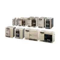
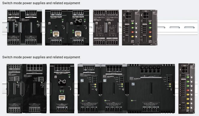
Harmonized design and side-by-side mounting help delivering more compact control panels with additional functionality.

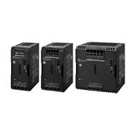
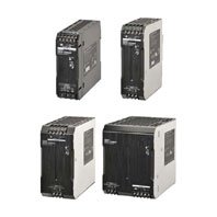
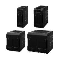
S8VK-WB
產品特色
Even more compact three-phase 380 to 480 V input power supplies. Reduces wiring work with the Push-In Plus terminals. With a line-up that includes 24 VDC and 48 VDC models.
Saving Space and More-advanced Control Panels
Uniform height reduces dead space and enables control panel downsizing

The switch mode power supply, noise filter, and DC electronic circuit protector, all compliant with the “Value Design for Panel” concept, are made to be uniform in height to reduce dead space and enable control panel downsizing.
Shortening Lead Time for Control Panel Building
With its extensive product lineup and features such as electrical control CAD support and status visualization, the S8VK Series helps streamline processes in building equipment and control panels.
[Design]
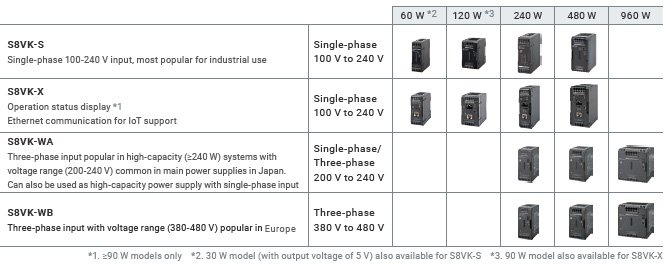
Extensive array of products with different input specifications and capacities significantly reduces selection effort
The S8VK Series offers both models with single phase (200-240 V) input and those with the more popular high-capacity three-phase input, allowing you to significantly reduce selection effort: just select a product with the input voltage and capacity best suited for your purpose.
eCAD library provided for all models greatly reduces design work

OMRON provides the libraries for over 48,000 models*4, highest in the industry, to achieve the great reduction of works for electrical design drawing and data creation.
*4. In the case of EPLAN, based on OMRON’s investigation as of 2020 December
*5. In the case of ZUKEN E3 series
eCAD Partners
By cooperating with various partners, we offer you more choices for your eCAD solutions.

E3.series is a product name of Zuken Inc. for their Electrical and Control Cable Design Solution.
EPLAN is a registered trademark of EPLAN Software & Service GmbH & Co. KG.
[Shipment/Operation]
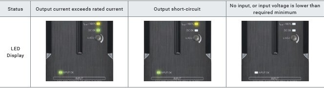
LED indicators visualize input power supply / output current status, allowing for faster check-ups upon startup or during operation
[S8VK-WA/WB]
S8VK-W power supplies notify users of their input voltage / load status via LED indicators and signal output. This clarifies failure status and required actions, allowing users to troubleshoot more quickly upon startup or during operation.
Stable operation in a wide range of environments
With excellent vibration and environmental resistance, S8VK power supplies can be used in a wide range of environments.
Issues in stable control panel operation
With the global expansion of production sites, control panels are expected to operate stably in vastly different environments

Control panels must comply with standards mandatory in their respective destinations

Excellent vibration resistance enables stable operation
The S8VK Series enables stable facility operation even in environments with significant vibration.
Vibration resistance enables safe transport as well as reliable operation
Robustly designed for 5G vibration resistance twice the resistance of conventional industrial power supplies.
S8VK power supplies can be safely transported by ship or over rugged terrain.

Can operate in a wide range of temperatures, from areas of extreme cold to the hot location
Ambient operating temperature of -40°C to 70°C

Can operate in highly humid / dusty environments
Operating humidity of up to 95%; PCBs coated for higher protection from dust

Can operate in high altitude environments with low atmospheric pressure
Complies with safety standards even at 3,000 m altitude *1

Supports global expansion of production sites through standard compliance and regulations
Complies with major standards such as UL and CSA as well as CE mark and other standards mandatory in specific regions for reliable use almost anywhere in the world. *1

*1. Refer to the datasheet of each product for information on supported standards.
Model Number Structure
Model Number Legend
Not all combinations are possible. Refer to List of Models in Ordering Information, below.
Ordering Information
List of Models
| Power rating |
Rated input voltage | Rated output voltage (VDC) |
Rated output current |
Maximum boost current |
Model |
|---|---|---|---|---|---|
| 240 W | Three-phase / two-phase 380 to 480 VAC (Allowable range: Three-phase / two-phase 320 to 576 VAC, 450 to 810 VDC) |
24 V | 10 A | 15 A | S8VK-WB24024 |
| 48 V | 5 A | 7.5 A | S8VK-WB24048 | ||
| 480 W | 24 V | 20 A | 30 A | S8VK-WB48024 | |
| 48 V | 10 A | 15 A | S8VK-WB48048 | ||
| 960 W | 24 V | 40 A | 60 A | S8VK-WB96024 | |
| 48 V | 20 A | 30 A | S8VK-WB96048 |
Accessories (Order separately)
Mounting Brackets (Order Separately)
| Product name | Model |
|---|---|
| Front Mounting Bracket (for 240 W) | S82Y-VKW20F |
| Front Mounting Bracket (for 480 W) | S82Y-VKW40F |
| Front Mounting Bracket (for 960 W) | S82Y-VKW90F |
DIN Rail Mounting Parts (Order Separately)
| Part name | Model |
|---|---|
| Support Rail (Aluminum) | PFP-100N |
| PFP-50N | |
| PFP-100N2 | |
| End Plate | PFP-M |
Ratings, Characteristics, and Functions
| Power rating | 240W | 480W | 960W | ||
|---|---|---|---|---|---|
| Output voltage | 24V | 24V | 24V | ||
| Efficiency *1 | Three-phase 400 VAC input | 93% typ. | 94% typ. | 95% typ. | |
| Two-phase 400 VAC input | 93% typ. | 94% typ. | 95% typ. | ||
| Input conditions |
Input voltage range *2 | Three-phase/two-phase 320 to 576 VAC, 450 to 810 VDC |
|||
| Frequency *2 | 50/60 Hz (47 to 63 Hz) | ||||
| Input current *1 | Three-phase 400 VAC input | 0.41 A typ. | 0.79 A typ. | 1.6 A typ. | |
| Two-phase 400 VAC input | 0.75 A typ. | 1.5 A typ. | 3.0 A typ. | ||
| Power factor *1 | Three-phase 400 VAC input | 0.9 min. | |||
| Leakage current *3 |
Three-phase 400 VAC input | 3.5 mA max. | |||
| Inrush current *4 | Three-phase 400 VAC input | 1.9 A typ. | 3.3 A typ. | 10.6 A typ. | |
| Output character- istics |
Rated output current | 10 A | 20 A | 40 A | |
| Power Boost Function | 15 A | 30 A | 60 A | ||
| Voltage adjustment range *5 | 24 to 29.5 V (with V.ADJ) | 24 to 28 V (with V.ADJ) |
|||
| Ripple noise voltage *6 |
Three-phase 380 to 480 VAC input |
100 mV p-p max. at 20 MHz of bandwidth |
80 mV p-p max. at 20 MHz of bandwidth |
50 mV p-p max. at 20 MHz of bandwidth |
|
| Input variation influence *7 | 0.5% max. | ||||
| Load variation influence *8 | 1.5% max. | ||||
| Temperature variation influence |
200 to 240 VAC input | 0.05%/°C max. | |||
| Startup time *9 | Three-phase 400 VAC input | 1,000 ms max. | |||
| Output hold time *9 |
Three-phase 400 VAC input | 30 ms typ. | 25 ms typ. | 20 ms typ. | |
| Additional functions |
Overload protection | Yes, automatic reset, intermittent operation type Refer to Overload Protection on below. |
|||
| Overvoltage protection | Yes, 130% or higher of rated output voltage, power shut off (shut off the input voltage and turn on the input again), Refer to Overvoltage Protection on below. |
||||
| Series operation | Yes (For up to two Power Supplies; external diodes required.) |
||||
| Parallel operation | Yes (For up to two Power Supplies), Refer to Parallel Operation on Data Sheet. |
||||
| INPUT OK Indicator | Yes (LED: Green) | ||||
| DC OK Indicator | Yes (LED: Green) | ||||
| Iout > 100% Indicator | Yes (LED: Yellow) | ||||
| DC OK Signal Output | Yes (MOS FET relay output 30 VDC max., 50 mA max.) | ||||
| Iout > 100% signal output | Yes (MOS FET relay output 30 VDC max., 50 mA max.) | ||||
| Insulation | Withstand voltage | 3.0 kVAC for 1 min. (between all input terminals and all output terminals, signal output terminals), cutoff current 20 mA |
|||
| 2.5 kVAC for 1 min. (between all input terminals and PE terminals), cutoff current 30 mA |
|||||
| 1.0 kVAC for 1 min. (between all output terminals, signal output terminals and PE terminals), cutoff current 25 mA |
|||||
| 0.5 kVAC for 1 min. (between all output terminals and all signal output terminals), cutoff current 10 mA |
|||||
| Insulation resistance | 100 MΩ min. (between all output terminals, signal output terminals and all input terminals / PE terminals) at 500 VDC |
||||
| Environ- ment |
Ambient operating temperature *10 | -40 to 70°C (Derating is required according to the temperature. Refer to Engineering Data on Data Sheet.) (with no condensation or icing) |
|||
| Storage temperature | -40 to 85°C (with no condensation or icing) | ||||
| Ambient operating humidity | 95% max. (Storage humidity: 95% max.) | ||||
| Vibration resistance | 10 to 55 Hz, maximum 5 G, 0.42 mm single amplitude for 2 h each in X, Y, and Z directions |
||||
| Shock resistance | 294 m/s2, 3 times each in ±X, ±Y, ±Z directions | ||||
| Reliability | MTBF *11 | 170,000 hrs typ. | 160,000 hrs typ. | 140,000 hrs typ. | |
| Expected life *12 | 10 years min. | ||||
| Construc- tion |
Weight | 890 g max. | 1,200 g max. | 1,800 g max. | |
| Cooling fan | No | ||||
| Degree of protection | IP20 by EN/IEC 60529 | ||||
| Power rating | 240W | 480W | 960W | ||
|---|---|---|---|---|---|
| Output voltage | 48V | 48V | 48V | ||
| Efficiency *1 | Three-phase 400 VAC input | 93% typ. | 94% typ. | 96% typ. | |
| Two-phase 400 VAC input | 93% typ. | 94% typ. | 95% typ. | ||
| Input conditions |
Input voltage range *2 | Three-phase/two-phase 320 to 576 VAC, 450 to 810 VDC |
|||
| Frequency *2 | 50/60 Hz (47 to 63 Hz) | ||||
| Input current *1 | Three-phase 400 VAC input | 0.41 A typ. | 0.78 A typ. | 1.6 A typ. | |
| Two-phase 400 VAC input | 0.75 A typ. | 1.5 A typ. | 2.9 A typ. | ||
| Power factor *1 | Three-phase 400 VAC input | 0.9 min. | |||
| Leakage current *3 |
Three-phase 400 VAC input | 3.5 mA max. | |||
| Inrush current *4 | Three-phase 400 VAC input | 1.7 A typ. | 3.0 A typ. | 10.5 A typ. | |
| Output character- istics |
Rated output current | 5 A | 10 A | 20 A | |
| Power Boost Function | 7.5 A | 15 A | 30 A | ||
| Voltage adjustment range *5 | 48 to 56 V (with V.ADJ) | ||||
| Ripple noise voltage *6 |
Three-phase 380 to 480 VAC input |
50 m V p-p max. at 20 MHz of bandwidth |
60 mV p-p max. at 20 MHz of bandwidth |
60 mV p-p max. at 20 MHz of bandwidth |
|
| Input variation influence *7 | 0.5% max. | ||||
| Load variation influence *8 | 1.5% max. | ||||
| Temperature variation influence |
380 to 480 VAC input | 0.05%/°C max. | |||
| Startup time *9 | Three-phase 400 VAC input | 1,000 ms max. | |||
| Output hold time *9 |
Three-phase 400 VAC input | 30 ms typ. | 25 ms typ. | 20 ms typ. | |
| Additional functions |
Overload protection | Yes, automatic reset, intermittent operation type Refer to Overload Protection on below. |
|||
| Overvoltage protection | Yes, 130% or higher of rated output voltage, power shut off (shut off the input voltage and turn on the input again), Refer to Overvoltage Protection on below. |
||||
| Series operation | Yes (For up to two Power Supplies; external diodes required.) |
||||
| Parallel operation | Yes (For up to two Power Supplies), Refer to Parallel Operation on Data Sheet. |
||||
| INPUT OK Indicator | Yes (LED: Green) | ||||
| DC OK Indicator | Yes (LED: Green) | ||||
| Iout > 100% Indicator | Yes (LED: Yellow) | ||||
| DC OK Signal Output | Yes (MOS FET relay output 30 VDC max., 50 mA max.) | ||||
| Iout > 100% signal output | Yes (MOS FET relay output 30 VDC max., 50 mA max.) | ||||
| Insulation | Withstand voltage | 3.0 kVAC for 1 min. (between all input terminals and all output terminals, signal output terminals), cutoff current 20 mA |
|||
| 2.5 kVAC for 1 min. (between all input terminals and PE terminals), cutoff current 20 mA |
|||||
| 1.0 kVAC for 1 min. (between all output terminals, signal output terminals and PE terminals), cutoff current 30 mA |
|||||
| 0.5 kVAC for 1 min. (between all output terminals and all signal output terminals), cutoff current 10 mA |
|||||
| Insulation resistance | 100 MΩ min. (between all output terminals, signal output terminals and all input terminals / PE terminals) at 500 VDC |
||||
| Environ- ment |
Ambient operating temperature *10 | -40 to 70°C (Derating is required according to the temperature. Refer to Engineering Data on Data Sheet.) (with no condensation or icing) |
|||
| Storage temperature | -40 to 85°C (with no condensation or icing) | ||||
| Ambient operating humidity | 95% max. (Storage humidity: 95% max.) | ||||
| Vibration resistance | 10 to 55 Hz, maximum 5 G, 0.42 mm single amplitude for 2 h each in X, Y, and Z directions |
||||
| Shock resistance | 294 m/s2, 3 times each in ±X, ±Y, ±Z directions | ||||
| Reliability | MTBF *11 | 170,000 hrs typ. | 160,000 hrs typ. | 140,000 hrs typ. | |
| Expected life *12 | 10 years min. | ||||
| Construc- tion |
Weight | 890 g max. | 1,200 g max. | 1,800 g max. | |
| Cooling fan | No | ||||
| Degree of protection | IP20 by EN/IEC 60529 | ||||
| Output voltage (VDC) | 24 V/48 V | 24 V/48 V | 24 V/48 V | ||
|---|---|---|---|---|---|
| Standards *14 |
Harmonic current emissions | Conforms to EN 61000-3-2 (three-phase/two-phase) *13 | |||
| EMI | Conducted emissions | Conforms to EN 61204-3 Class B, EN 55011 Class B (three-phase) Conforms to EN 61204-3 Class A, EN 55011 Class A (two-phase) |
|||
| Radiated emissions | |||||
| EMS | Conforms to EN 61204-3 high severity levels | ||||
| Safety standards | UL 508 Listing UL 62368-1 (Recognition) OVC II (≤ 3000 m) Pol2 CSA C22.2 No.62368-1 OVC II (≤ 3000 m) Pol2 EN/IEC 62477-1 OVC III (≤ 2000 m) OVC II (2000 m < and ≤ 3000 m) Pol2 EN/IEC 62368-1 OVC II (≤ 3000 m) Pol2 EAC (TR CU 004 / 2011, TR CU 020 / 2011) RCM (EN61000-6-4) Complies with PELV (EN/IEC 60204-1) Complies with EN/IEC 61558-2-16 BIS (IS13252 (Part1): 2010) |
||||
| SEMI | Complies with SEMI F47-0706 (three-phase 380 to 480 VAC input) | ||||
*1. The value is when both rated output voltage and rated output current are satisfied.
*2. Do not use an inverter output for the product. Inverters with an output frequency of 50/60 Hz are available, but the rise
in the internal temperature of the product may result in ignition or burning. If the input is connected to a UPS, do not
connect a UPS with a square-wave output. Doing so will cause the internal temperature of the product to increase,
possibly causing smoking or burning.
*3. The value is determined according to the Electrical Appliances and Material Safety Act.
*4. Values for a cold start at 25°C. Refer to Inrush Current, Startup Time, and Output Hold Time on below.
*5. If the output voltage adjuster (V. ADJ) is turned, the voltage will increase by more than the voltage adjustment range.
When adjusting the output voltage, confirm the actual output voltage from the product and be sure that the load is not
damaged.
*6. The value is when both rated output voltage and rated output current are satisfied.
A characteristic when the ambient operating temperature is 25°C.
*7. This is the maximum variation in the output voltage when the input voltage is gradually changed within the allowable
input voltage range at the rated output voltage and rated output current.
*8. 380 to 480 VAC input, in the range of 0 A to the rated output current.
*9. This is the value when both rated output voltage and rated output current are satisfied and at room temperature (25°C).
Refer to Inrush Current, Startup Time, and Output Hold Time on below for details.
*10. At -40 to -25°C, time will be required before the rated output voltage is output after the input voltage is input.
*11. MTBF is calculated according to JEITA RCR-9102.
*12. Refer to Recommended Replacement Periods and Periodic Replacement for Preventive Maintenance on Data Sheet for
details.
*13. When using 2-phase input, conforms to EN 61000-3-2 under the following condition.
960W: At the rated output voltage, and 80% or less than the rated output current
*14. Refer to Standard Compliance below for details.
Standard Compliance
• To comply with PELV output requirements for EN/IEC 60204-1, ground the negative side of the output (-V) to a protective
earth (PE).
• EN/IEC 61558-2-16
The S8VK-WA was designed based on EN/IEC 61558-2-16.
Currently, IEC 61558-2-17 has been replaced by IEC 61558-2-16.
When certification was received for EN/IEC 60204-1 (Machinery Safety), it was necessary to go through a control
transformer to the control circuits. However, a control transformer is not always necessary for product that have been
certified for the safety standard for OVCIII or for product that use a transformer that complies with EN/IEC 61558-2-16.
• For the S8VK-WB, the DC input is not compliant with Safety standards.
• Only 480 W and 960 W models are compliant with BIS (IS 13252 (Part 1)).
Inrush Current, Startup Time, and Output Hold Time
Note: Twice the normal inrush current will flow during parallel operation or for backup operation. Therefore, check the fusing
characteristics of fuses and operating characteristics of breakers making sure that the external fuses will not burn out
and the circuit breakers will not be activated by the inrush current.
characteristics of fuses and operating characteristics of breakers making sure that the external fuses will not burn out
and the circuit breakers will not be activated by the inrush current.
Overload Protection
The product is automatically protected from short-circuit current and overcurrent damages when the load current is in the range of 151 to 175% of the rated current.
When the output current falls within the rated range, the overload protection function is automatically cleared.
Note: 1. Internal parts may occasionally deteriorate or be damaged if a short-circuited or overcurrent state continues during
operation. Be sure to check that the Iout > 100% indicator is not lit or the Iout > 100% signal output is turned OFF
before using.
2. Internal parts may possibly deteriorate or be damaged if the Power Supply is used for applications with inrush
current or overloading at the load end. Do not use the Power Supply for such applications.
Overvoltage Protection
Overvoltage will be detected to prevent the load from being subjected to excessive voltage when the feedback circuit in the Power Supply fails, etc.
When an excessive voltage that is approximately 130% of the rated output voltage or more is output, the output voltage is cut OFF, preventing damage to the load due to overvoltage.
Reset the input power by turning it OFF for at least three minutes and then turning it back ON again.
Note: Do not turn ON the power again until the cause of the overvoltage has been removed.
INPUT OK Indicator
The INPUT OK indicator will light when the input voltage exceeds the lower limit value of the permissible range.
Note: The voltage may be applied even if the indicator does not light.
Be sure to check the input voltage when performing wiring.
Note: The voltage may be applied even if the indicator does not light.
Be sure to check the input voltage when performing wiring.
DC OK Indicator/Signal Output
The DC OK indicator will light when the output voltage is more than 90% of the rated output voltage, and the internal MOS FET relay is conducted (turned ON).
Note: 1. The output voltage may be generated even if the indicator does not light. Be sure to check the output voltage when
connecting to the load.
2. This function monitors the voltage at the power output terminals.
To check the voltage accurately, measure the voltage at the load end.
3. If the output voltage is set to less than 90% of the rated output voltage, the indicator may go off and the signal
output may be turned OFF.
Iout > 100% Indicator/Signal Output
The Iout > 100% indicator lights up when the output current exceeds the rated output current, and the internal MOS FET relay is conducted (turned ON).
Note: 1. The Iout > 100% Indicator may light up, and the Iout > 100% Signal Output may turn ON during peak current
operation, however, the Power Supply can be used as long as the operating conditions specified in Peak current
(Data Sheet) are satisfied.
2. Even when the operating conditions for parallel operation are satisfied, the Iout>100% Indicator / Signal Output
may operate, so do not use the Iout>100% Indicator / Signal Output.
3. During a short-circuit, the indicator will operate intermittently due to the overload protection function. When this
happens, the indicator will blink in accordance with the intermittent operation, and the Iout > 100% signal output
will repeated turn ON and OFF.
The shortest ON time of the Iout > 100% signal output during intermittent operation is 5 ms.
Specifications of the Signal Output Terminals (between DC OK Signal Output Terminal and COM Terminal, and between Iout > 100% Signal Output Terminal and COM Terminal)
Since the Signal Output is composed of the MOS FET relay, it does not have any polarity.
30 VDC max., 50 mA max.
Residual voltage when the function is ON: 2 V max.
Leakage current when the function is OFF: 0.1 mA max.
Note: 1. Internal current control circuits are not provided internally for output signals. Do not allow the output current to
exceed 50 mA.
2. After completing wiring, confirm that the circuits operate correctly.
Identification of error locations at the input, product, and load side by the Indicator or Signal Output, and troubleshooting for the same (Maintenance point indicator)
Error locations at the input, product, and load side can be identified by the INPUT OK, DC OK, Iout > 100% Indicator / Signal Output.

Time chart (Operation of the Indicator/Signal Output according to the product status)

(單位:mm)
S8VK-WB240[][]
S8VK-WB480[][]
S8VK-WB960[][]
Mounting Brackets (Order Separately)
Note: The front mounting bracket can be used for front, side-by-side mounting as well.
DIN Rail Mounting (Order Separately)
Mounting Rail (Material: Aluminum)
PFP-100N
PFP-50N
PFP-100N2
End Plate
PFP-M
Note: 1. If there is a possibility that the Unit will be subject to vibration or shock, use a steel DIN Rail. Otherwise, metallic
filings may result from aluminum abrasion.
2. If the Unit may be subjected to sliding to either side, attach an End Plate (PFP-M) on each side of the Unit.
filings may result from aluminum abrasion.
2. If the Unit may be subjected to sliding to either side, attach an End Plate (PFP-M) on each side of the Unit.
English
Global Edition
| Catalog Name | Catalog Number [size] |
Last Update | |
|---|---|---|---|
| T219-E1-08 [8113KB] |
Jun 20, 2022
20220620
|
S8VK-W Data Sheet | |
| T235-E1-02 [7963KB] |
Aug 02, 2021
20210802
|
S8VK-S/S8VK-W/S8VK-X Catalog | |
| Y235-E1-01 [5944KB] |
Jul 19, 2022
20220719
|
Value Design for Panel Catalog |
如有需要請洽各所營業人員
誠睿台南所 TEL:06-2493086
誠睿台中所 TEL:04-23380790
誠睿新竹所 TEL:03-6685558
客服信箱 service@hitifa.com.tw
誠睿台南所 TEL:06-2493086
誠睿台中所 TEL:04-23380790
誠睿新竹所 TEL:03-6685558
客服信箱 service@hitifa.com.tw
如有需要請洽各所營業人員
誠睿台南所 TEL:06-2493086
誠睿台中所 TEL:04-23380790
誠睿新竹所 TEL:03-6685558
客服信箱 service@hitifa.com.tw
誠睿台南所 TEL:06-2493086
誠睿台中所 TEL:04-23380790
誠睿新竹所 TEL:03-6685558
客服信箱 service@hitifa.com.tw